TM3160F,TM3200F&TM3240F
46
Detaching Implements
CAUTION: Always use POSITION CONTROL
to attach / detach implements to provide pre-
cise control of the hitch.
Select a level to detach and store the implement.
Lower implement to ground by moving the position
control lever to DOWN. If necessary, adjust the levelling
crank on the right lift link to level the implement on
ground.
Shut off the engine, securely lock the brakes and
remove the main switch key from the tractor.
Disconnect the implement PTO driveshaft (as applica-
ble). Detach the top link from the implement.
NOTE: Lengthening or shortening of the top link may be
required to permit disconnection from the imple-
ment.
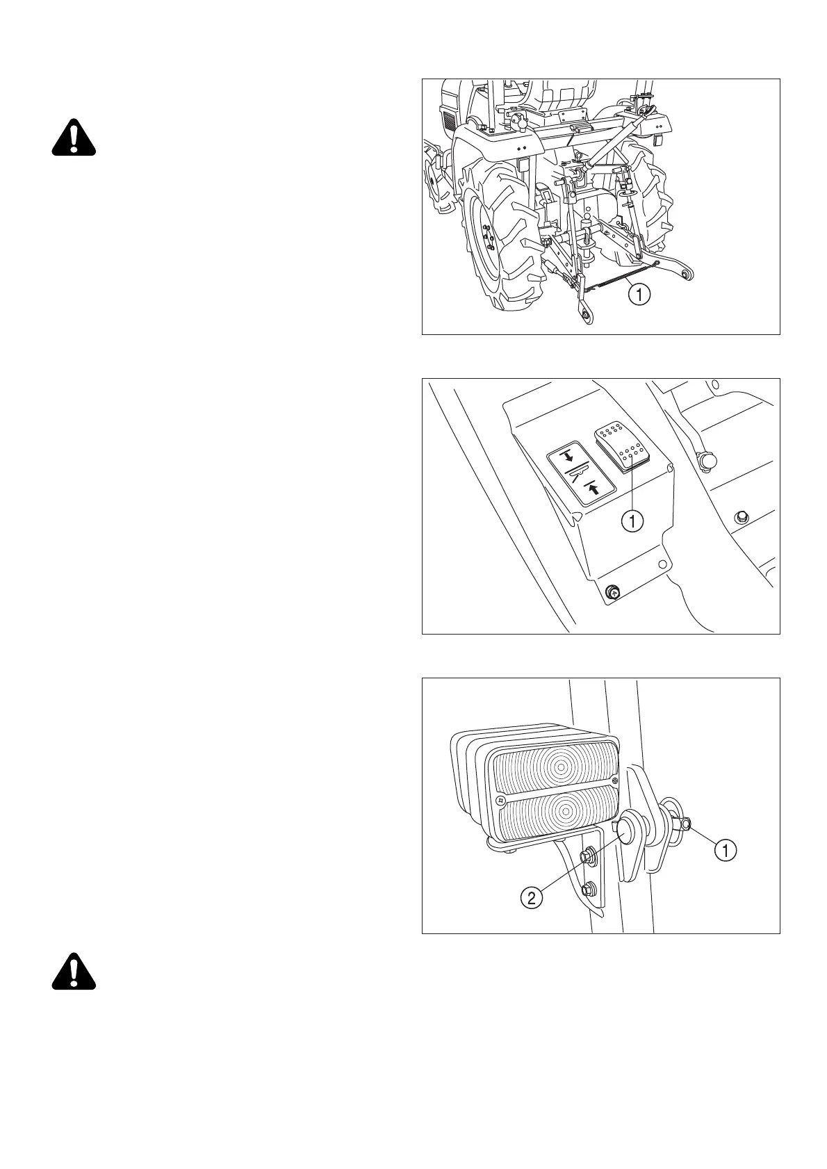
FIG. 60: Disconnect the lower links from the imple-
ment pins. Make sure the lower links are connected
together with the spring (1) to prevent tyre interference.
Take position in the operator's seat, start the engine
and drive the tractor clear of the implement.
Mower up-down control (OPTION)
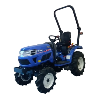
FIG. 61: Mower deck is lifted and lowered or hydraulic
cylinder under right side fender. It is controlled by this
seesaw type switch, (1).
NOTE: The mower deck is equipped with cutting height
control.
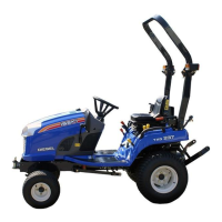
Roll Over Protect in Structure (ROPS)
Tractor is equipped with fold-down ROPS which can
be folded down and the Tractor functionally used in that
condition for low clearance situation such as orchards,
vineyards, barns, and chicken houses, etc.
Always raise ROPS in to the fully erect position at the
earliest time.
ROPS must be maintained in this fully raised position
at all times unless practical operation of the tractor dic-
tates other wise, (as described above).
How to Tilt ROPS
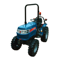
FIG. 62: Remove linchpin, (1), remove pin, (2) , and
tilt the ROPS rearward care fully.
CAUTION: Do not weld, drill, bend or straight-
en. Make sure all components are in correct
working order to provide the intended protec-
tion.
Only original bolts, or equivalent replace-
ments, must be used and tightened to correct
torque value Make sure both "hinge" joints
are properly secured.
FIG. 60
FIG. 61
FIG. 62



 To Next Page