TM3160F,TM3200F&TM3240F
66
Wiring / Fuse Arrangement
CAUTION: Keep all wiring connections clean
and tight. Make sure wiring is correctly
secured to prevent damage.
CAUTION: DO NOT alter wiring by adding
"home-made" extensions or replacements.
Doing so can eliminate fuse protection and /
or eliminate safety features of the system.
CAUTION: The tractor is equipped with nega-
tive (-) ground system. Tractor metal parts
provide many electrical connections. For this
reason, all positive (+) circuits must be insu-
lated to prevent "earthing" or short circuits
and prevent possible fire.
CAUTION: DO NOT replace any fuse with a
fuse of higher amperage rating. DO NOT use
wire (or foil) to by-pass fuse protection. Fire
can result. If fuses blow repeatedly, examine
the electrical system for "earthed" or "short-
ed" circuits.
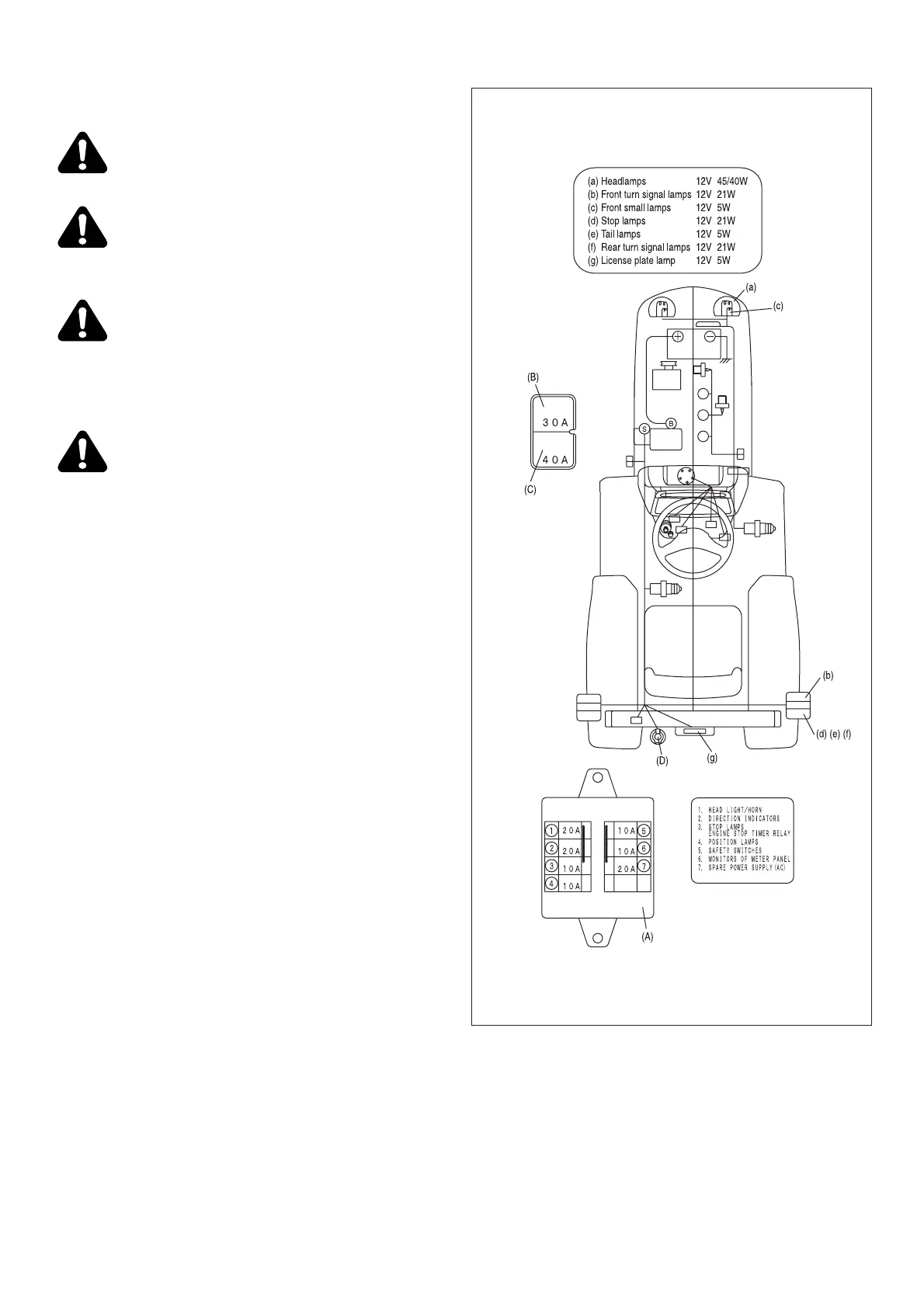
FIG. 97: General layout and location of electrical sys-
tem components and fuses:
• Main Fuse Box, A - Located inside left hand fan
cover.
• 30 Amp. Slow Blow Fuse B - A pink slow blow fuse
is located in the charging circuit. If it falls to function,
it will cause the battery to become discharged. If fail-
ure occurs, be certain to locate and correct the
cause of failure before replacing fuse A blown fuse
will have swollen and / or discolored insulation.
IMPORTANT: Slow blow fuses are of specific Use only
authorized parts for replacements.
• 40 Amp. Slow-Blow Fuse C - is located in the main
wiring harness at front of starter. When it burns out
there will be no current flow through any of the
wiring. If failure occurs be certain to locate and cor-
rect the problem prior to installing a new fuse.
• 7-pin Trailer Socket D
NOTE: A special fuse is used-use only genuine ISEKI
parts.
WIRING DIAGRAM
Please refer to the folder bound at the end of this
manual.
FIG. 97



 To Next Page