GENERAL ENGINE MECHANICAL 6A – 55
6. Piston and Connecting Rod
• Apply engine oil to the cylinder bores, the connecting
rod bearings and the crankshaft pins.
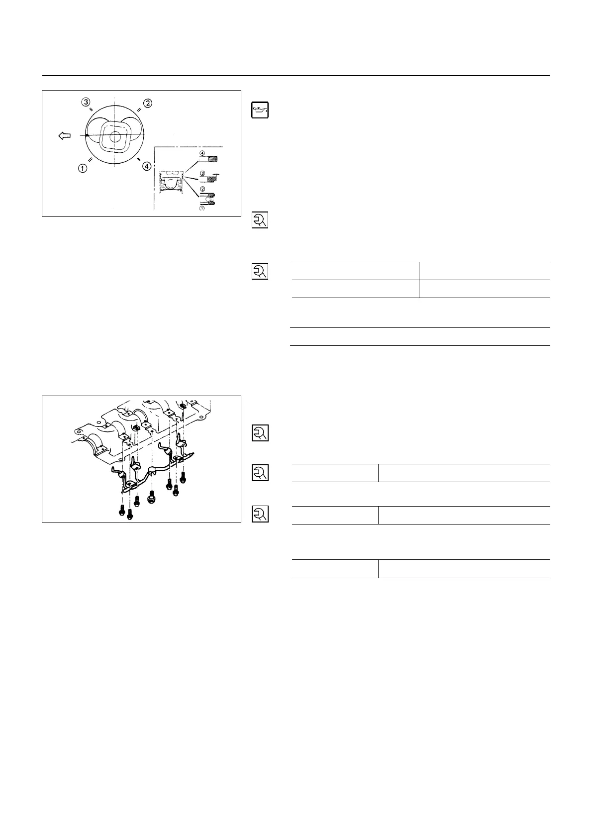
• Check to see that the piston ring end gaps are
correctly positioned.
• Insert the piston/connecting rod assemblies into each
cylinder with the piston ring compressor.
• The front marks must be facing the front of the engine.
5. Connecting Rod Bearing Cap
• Tighten the cap nuts in 2 steps, using angular
tightening method as shown in the following
specifications.
4JG2 N∙m (kg∙m/lb∙ft)
1st Steps 2nd Step
29 (3.0/22) 45° - 75°
4JA1, 4JB1, 4JB1TC N∙m (kg∙m/lb∙ft)
83 (8.5/61)
After tightening the cap nuts, check to see that the
crankshaft rotates smoothly.
4. Piston Cooling Oil Pipe
• Install the piston cooling oil pipe to the cylinder body.
• Tighten the oil pipe bolts and relief valve to the
specified torque.
Oil Pipe Bolt Torque N∙m (kg∙m/lb∙ft)
(1) M8 x 1.25 19 (1.9/14)
N∙m (kg∙m/lb∙in)
(2) M6 x 1.00 8 (0.8/69)
Oil Pressure Regulating
Valve Torque N∙m (kg∙m/lb∙ft)
(3) M16 x 1.5 29 (3.0/22)
NOTE:
Check that there is no interference between the piston
and the oiling jet pipe by slowly rotating the
crankshaft.
3. Oil Pump Assembly
2. Oil Pan Assembly
Above works refer to “OIL PUMP” Section in this manual.
1. Cylinder Head Assembly
• Piston Head Projection Measurement Point
• Cylinder Head ASM
• Push Rod
• Rocker Arm Shaft ASM
Valve clearance adjustment.
Above works refer to “CYLINDER BLOCK” Section in this
manual.
6A-55-1.tif
6A-55-2.tif
 Loading...


