Digital Network Public Address & Voice Alarm System
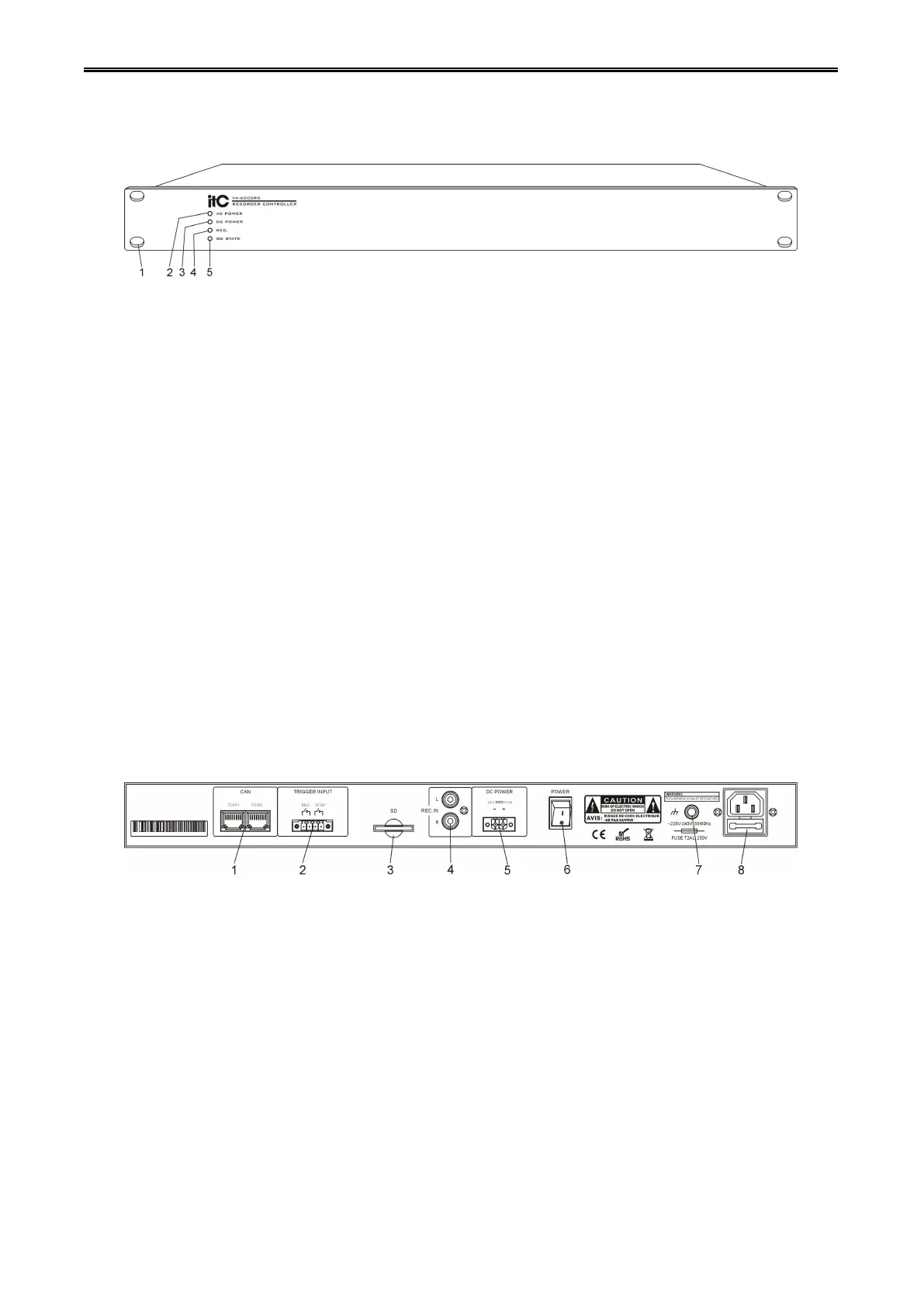
1. 19 inch cabinet location hole.
2. The main power indicator:
Green - main power supply is normal.
Yellow - mains power supply is failure.
3. Standby 24V DC power indicator:
Green - standby power supply is working normally.
Off - does not detect the standby power supply.
4. Equipment recording status indicator:
Green - device is currently working on recording mode.
Off - device is not currently working on recording mode.
5. SD Card connection status indicator:
Green - SD card connection is normal.
Yellow - SD card connection has fault.
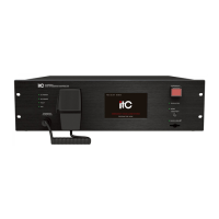
1. Equipment online CAN interface.
2. Relay contact trigger control interface(>=0.5S).
3. SD card connector, used for external storage SD card.
4. Recording audio input interface.
5. Standby 24V power supply interface.
6. Device power supply switch.
7. Cabinet ground contact point(Note: Please make sure this point contact ground reliable).
8. AC power input socket.