Quick Reference
and turning the knob anticlockwise indicates that the previous menu item is
selected.
Confirm settings
After completing the value setting or selecting a menu item, pushing the knob
acts like pressing [Enter] key to confirm the operation.
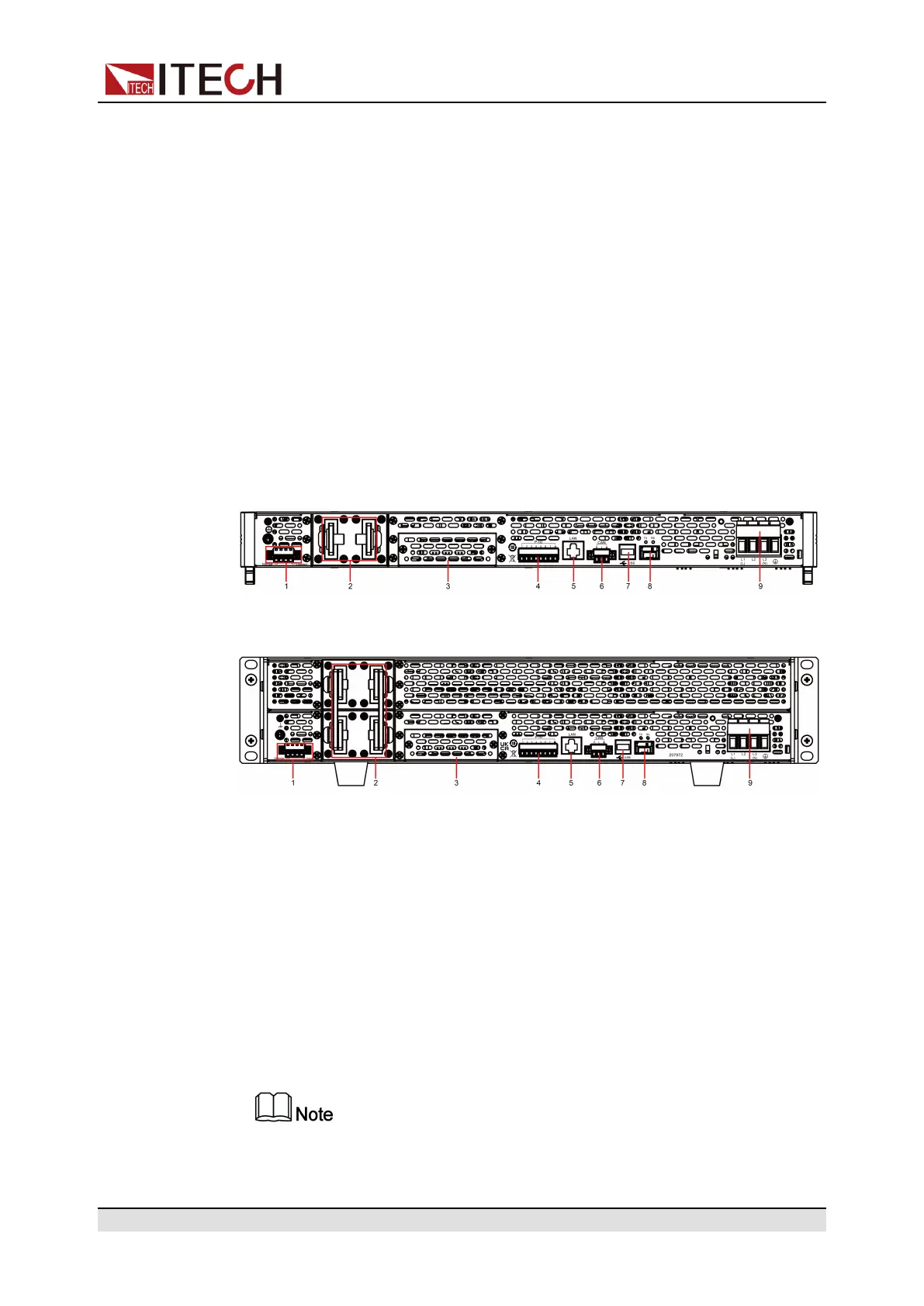
1.5 Rear Panel Introduction
The rear panel of the of the this series model (after removing the protective cov-
er) is shown below.
1U Models
2U Models
1. Sense terminals (Vs+, Vs-)
2. DC output terminals of the power supply
3. Interface for optional accessories IT-E176 and IT-E177 (For details, see 1.9
Options Introduction)
4. Digital I/O interface: P-IO
5. LAN communication interface
6. CAN communication interface
7. USB communication interface
8. Communication interface of outer ring optical fiber (TX and RX)
This interface is used for the parallel connection between the units for the
communication of units in parallel.
9. AC power input terminals (L1, L2, L3, and PE)
Copyright © Itech Electronic Co., Ltd.
8