Power Supply Function
Ri
a
(Ω)
0.5≤Ri≤4 1≤Ri≤8
t
d
(ms)
40≤t
d
≤400 100≤t
d
≤350
t
r
(ms)
– –
a
If not otherwise agreed, use the upper voltage level with the upper value for in-
ternal resistance or use the lower voltage level with the lower value for internal
resistance.
The following general considerations of the dynamic behavior of alternators dur-
ing load dump apply:
• The internal resistance of an alternator, in the case of load dump, is mainly a
function of alternator rotational speed and excitation current.
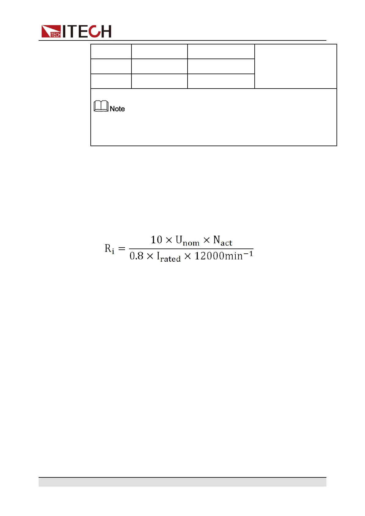
• The internal resistance, Ri, of the load dump test pulse generator shall be
obtained from the following relationship.
– U
nom
: The specified voltage of the alternator
– I
rated
: The specified current at an alternator speed of 6000r/min
– N
act
: The actual alternator speed, unit: round per minute (r/min)
• The pulse is determined by the peak voltage U
n
, the clamping voltage U
S
,
the internal resistance R
i
, and the pulse duration t
d
; in all cases small values
of U
n
are correlated with small values of R
i
and t
d
, and high values of U
n
with
high values of R
i
and t
d
. For the test voltage U
A
please refer to ISO16750-1.
How to recall this waveform from menu (take Test A 12V as an example):
1. Press the composite keys [Shift]+[I-set] (Function) on the front panel to en-
ter the function menu.
2. Use the knob or press the Up/Down key to select 3.Road-Vehicles = Off
and press [Enter].
3. Press the Left/Right key to select ISO16750-2 and press [Enter] to confirm.
4. Press the Left/Right key to select Load-Dump, and press [Enter] to confirm.
5. Press the Left/Right key to select Test A, and press [Enter] to confirm.
6. Press the Left/Right key to select 12V, and press [Enter] to confirm.
Copyright © Itech Electronic Co., Ltd.
99
ООО "Техэнком" Контрольно-измерительные приборы и оборудование www.tehencom.com
 Loading...

