Inspection and Installation
1. Remove the output terminal cover.
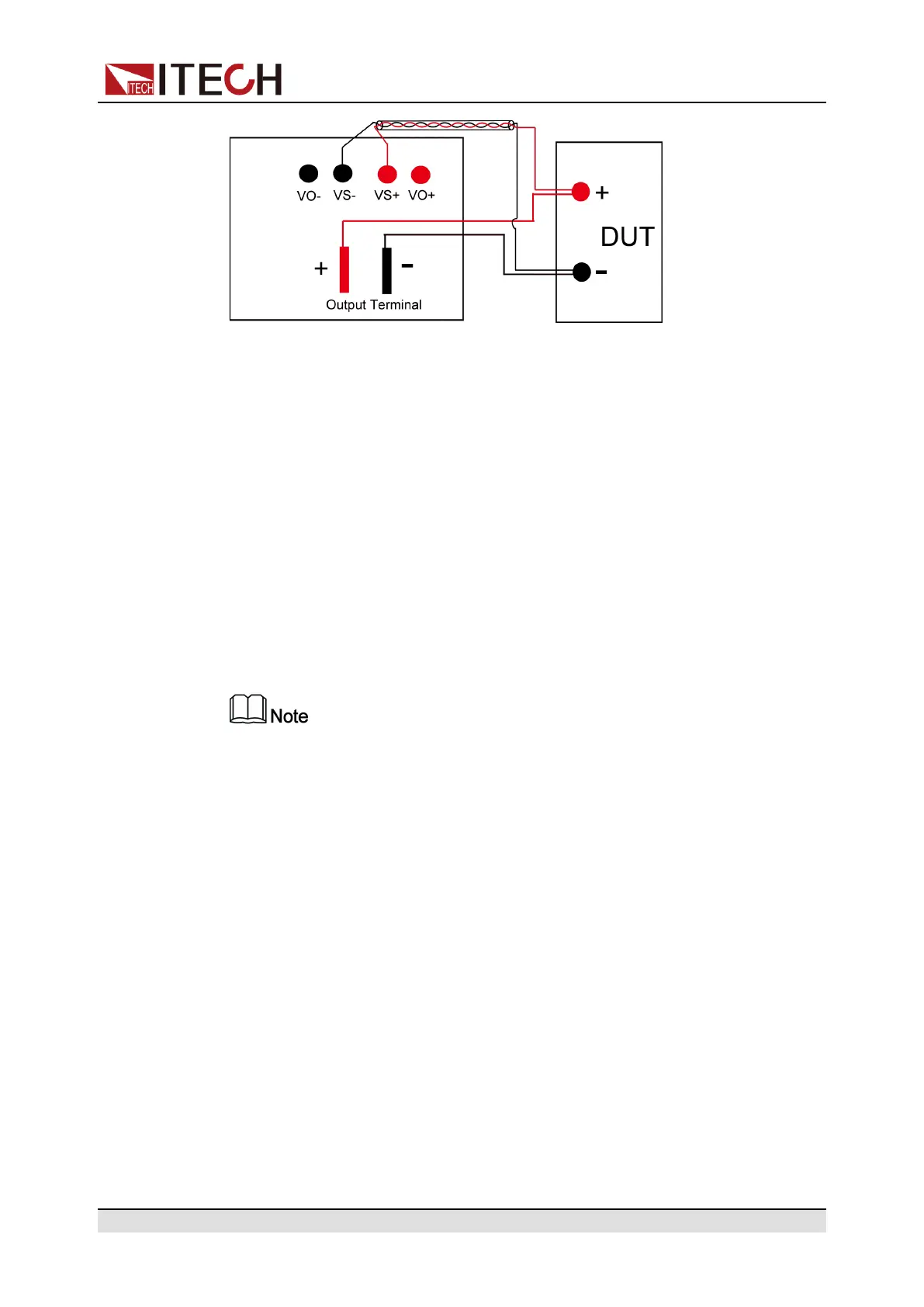
2. Disconnect the wires/short clips between Vo+ and Vs+, Vo- and Vs-.
3. Use armored twisted-pair cables to connect the remote sense terminals and
the equipment under test.
4. Loosen the screws of the output terminals and connect the red and black
test cables to the output terminals. Make proper connection of the chassis
ground. Re-tighten the screws.
When maximum current that one test cable can withstand fails to meet the
current rated current, use multiple pieces of red and black test cables. For
example, the maximum current is 1,200 A, then 4 pieces of 360 A red and
black cables are required.
5. Install the output terminal cover, leave the other end of remote sense cables
and the red and black cables outside.
6. Connect the other end of the remote sense cables and the red and black
cables to the DUT.
To ensure the stability of the system, use armored twisted-pair cables
between the remote sense terminals and the equipment under test.
Copyright © Itech Electronic Co., Ltd.
8