Function and Features
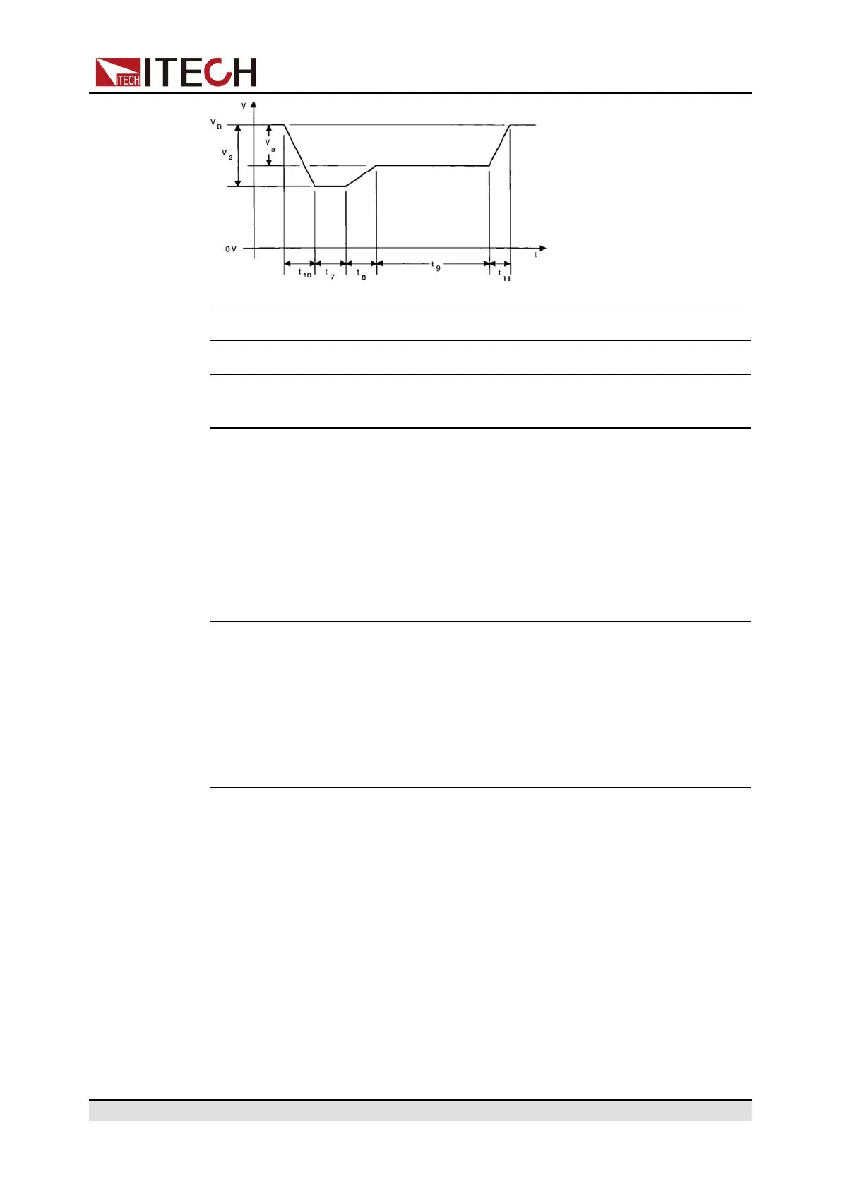
Parameters 12V System 24V System
V
S
(From V
B
) -4V to -7V -5V to -16V
V
a
(From V
B
) -2.5 to -6V with
IV
a
I≤IV
S
I
-5 to -12V with
IV
a
I≤IV
S
I
R
i
0Ω to 0.02Ω 0Ω to 0.02Ω
t
7
15 to 40ms
(1)
50 to 100ms
(1)
t
8
≤50ms ≤50ms
t
9
0.5 to 20s
(1)
0.5 to 20s
(1)
t
10
5ms 10ms
t
11
5 to 100ms
(2)
10 to 100 ms
(3)
1. The value used should be agreed between the vehicle manufacturer and
the equipment supplier to suit the proposed application.
2. t
11
=5 ms is typical of the case when engine starts at the end of the cranking
period, while t
11
=100 ms is typical of the case when the engine does not start.
3. t
11
=10 ms is typical of the case when engine starts at the end of the
cranking period, while t
11
=100 ms is typical of the case when the engine does
not start.
Test 5
For the details, please refer to the 3.20.2 simulate the waveform to verify the
anti-interference performance of the automotive electronics’ products.
3.20.5 LV124
IT6500C series all come with built-in curves which meet general requirements,
test conditions and tests of electrical and electronic components in motor
vehicles up to 3.5 t.
Copyright © Itech Electronic Co., Ltd.
68