Technical Specification
5. Up time and down time mean the time of establishment from one value to
another value under ON status when the internal standard power dissipater is
enabled.
6. Use 12V/120AH battery for test.
7. When used in parallel, to balance power of each phase, distribute the
instrument to three phases. But must ensure that single machine input voltage
meets Specification requirements.
8. It means the maximum phase current value under minimum work input
voltage.
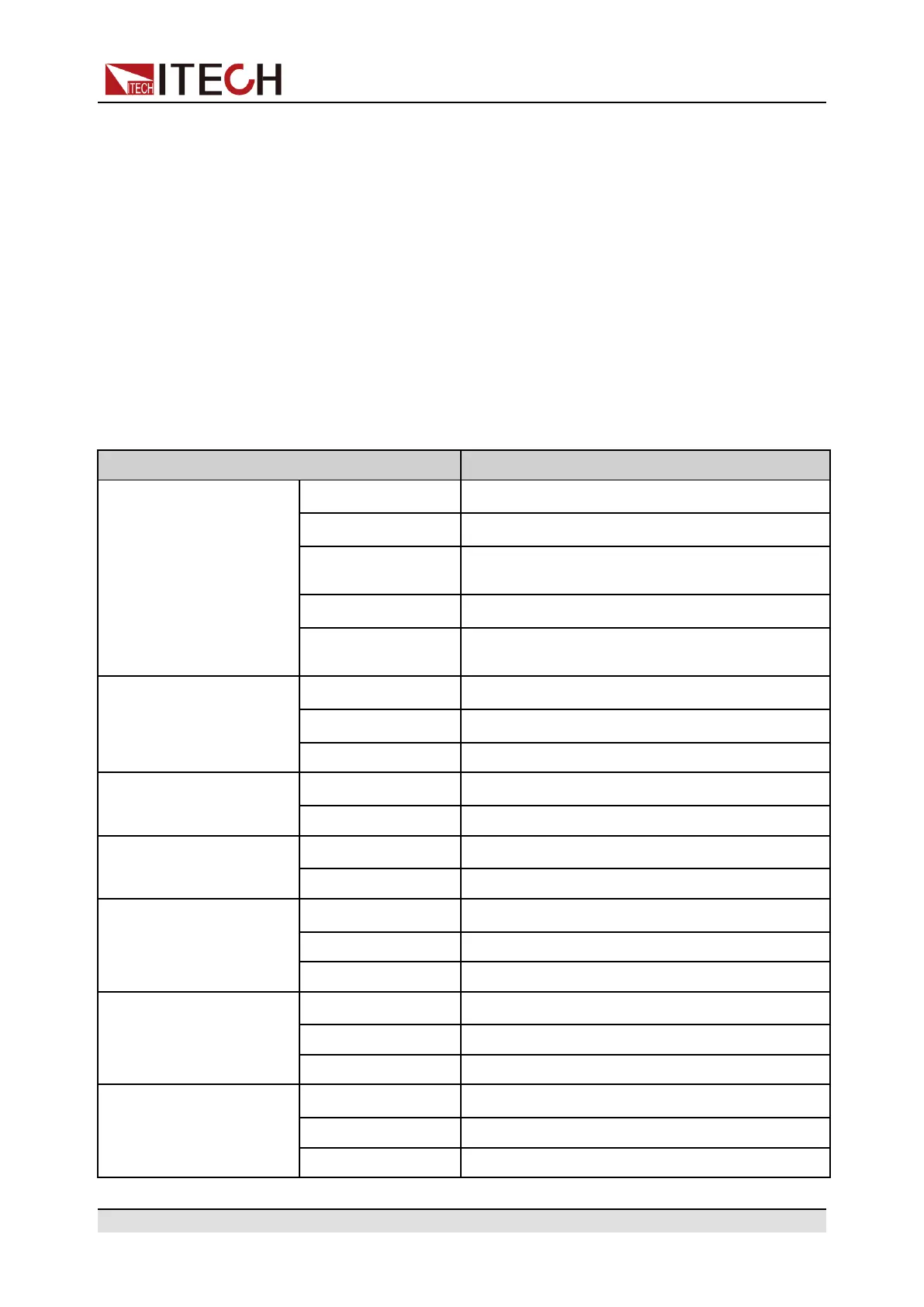
5.1.11 IT6525C
Parameter IT6525C Ver:V1.6
Output Rating ( 0 ℃-40
℃)
Output Voltage
0~500V
Output Current
0~20A
Internal Sink
Current
1
0~8A
Output Power
0~3000W
Internal Sink
Power
1
0~150W
Output Resistance
Range
0~83.33Ω
Accuracy
2
0.25%+200mΩ
Resolution 10mΩ
Line regulation
±(%of Output+Offset)
Voltage
≤0.01%+50mV
Current ≤0.01%+10mA
Load regulation
±(%of Output+Offset)
Voltage
≤0.01%+100mV
Current ≤0.05%+20mA
Setup Resolution
Voltage
100mV
Current 10mA
Power 0.1W
Read Back Resolution
Voltage
100mV
Current 10mA
Power 0.1W
Setup Accuracy
(within 12 months,25℃
±5℃)
±(%of Output+Offset)
Voltage
≤0.05%+200mV
Current ≤0.2%+20mA
Power ≤1%+30W
Copyright © Itech Electronic Co., Ltd.
120