Function and Features
7. Press [Shift]+[Enter] (Trigger) to generate a trigger signal. The DC source
will output Short voltage drop waveform. The Trig indicating lamp will be lit
and display on the VFD.
Please make sure the trigger source is selected in MANUAL item in above
operations(refer to step 7th).
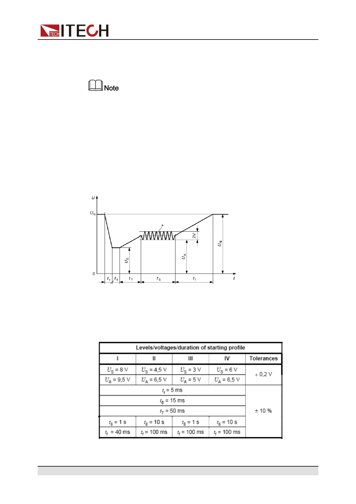
Starting Waveform
This test verifies the behavior of a DUT during and after cranking. Apply the
starting profile ten times, as specified in Figure and Table below simultaneously
to all relevant inputs (connections) of the DUT. A break of 1 s to 2 s between the
starting cycles is recommended. One or more profiles as described in Tables 3
and 4 shall be chosen in accordance with the application.
af=2HZ
• Standards for 12V system:
Curve should be selected based on actual test requirements. To create
waveform within 12V, follow the set standards as below:
• Standards for 24V system:
Copyright © Itech Electronic Co., Ltd.
60