Function and Features
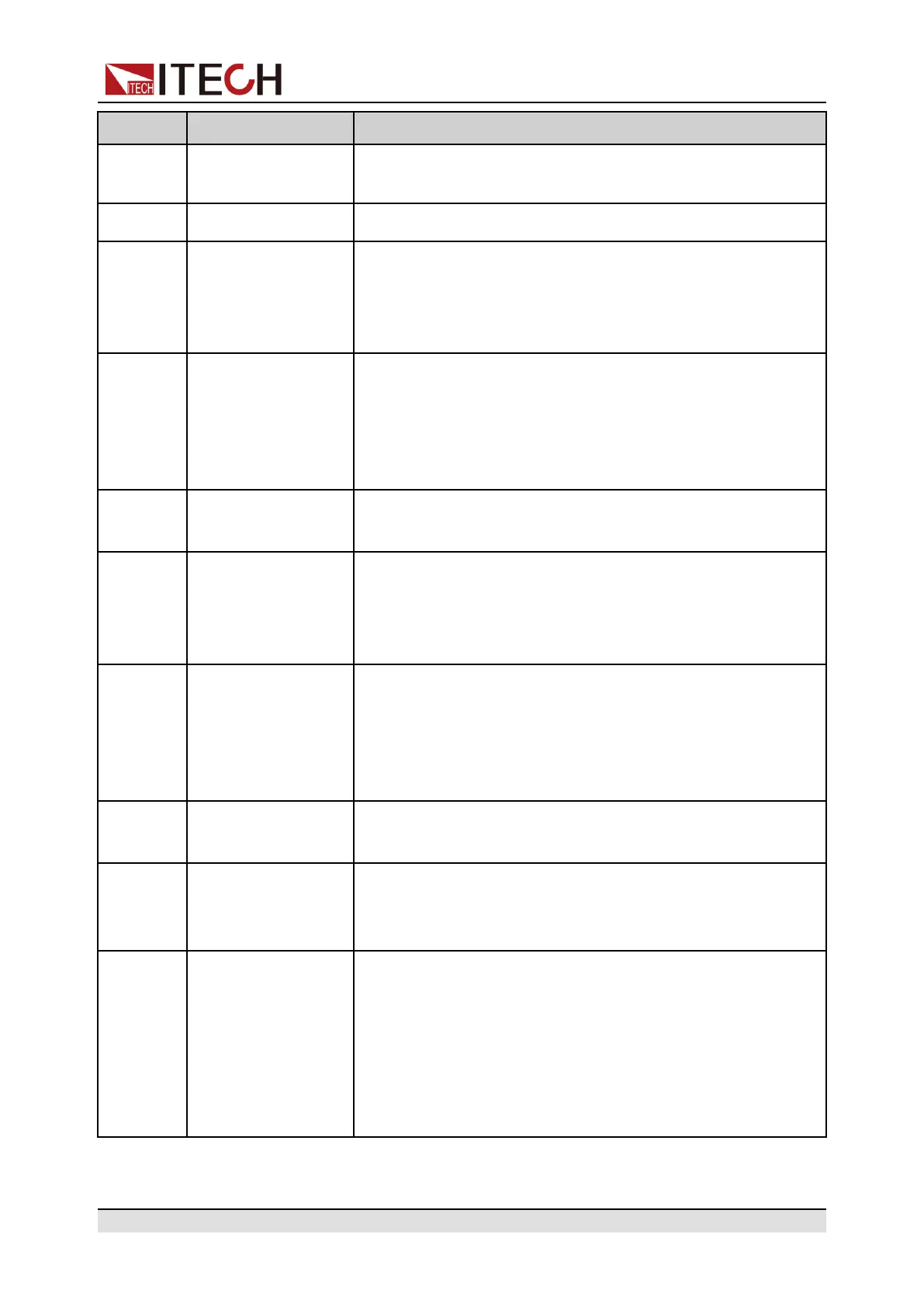
Pin Name Description
Pin 1 and
Pin 14
CANH
CANL
Pin 1 used for CAN H interface, and Pin 14 used for CAN L
interface.
Pin 2 +12V Power supply output 12V, driving capacity 0.1A
Pin 3 Shut Off Used for switching off the function under emergency status
(In general circumstances, the pin is suspended, and
defaulted to low level); when external high level is
connected, output is off.
Pin 15 EXT ON Used for controlling output On/Off of the power supply;
default setting is high level. Output is controlled by On/Off;
when external low level is connected, or when it is short
circuited to DGND, output is switched off. At this time, setting
of output On/Off fails.
Pin 16 Power OK Used for indicating whether the power output is normal; if so,
output 5V; in case of power supply failure, output 0V.
Pin 17 TrigIN Input signal of reverse protection mode. When input is low
level, alarm "OutPut Reverse Protect” fault.
At the mean while, in external trigger mode, when input is
low level, then actualize trigger function.
Pin 6 TrigOUT Output signal of reverse protection mode. When power
supply output is On, this pin outputs high level; when this
power supply output is Off, this pin outputs low level; it can
be used for synchronous control of On/Off for other devices
with driving capacity of 5V/5mA.
Pin 18 +5V The power supply outputs 5V voltage, which is used for
digital power supply with driving capacity of 0.1A.
Pin 19
and Pin
20
CV_CC+
CV_CC-
The output between these two pins is used for indicating the
working status of power supply; under CV mode, the output
between these two pins is 5V; and under CC mode, - 5V.
Pin 21 Voltage Program (
Voltage setting)
Output voltage of analog control:
In setting the Voltage and 10v, the input analog range should
be 0-10V voltage, and the regulated output voltage should be
from 0 to full range;
In setting the Voltage and 5v, the input analog range should
be 0-5V voltage, and the regulated output voltage should be
from 0 to full range;
Copyright © Itech Electronic Co., Ltd.
77