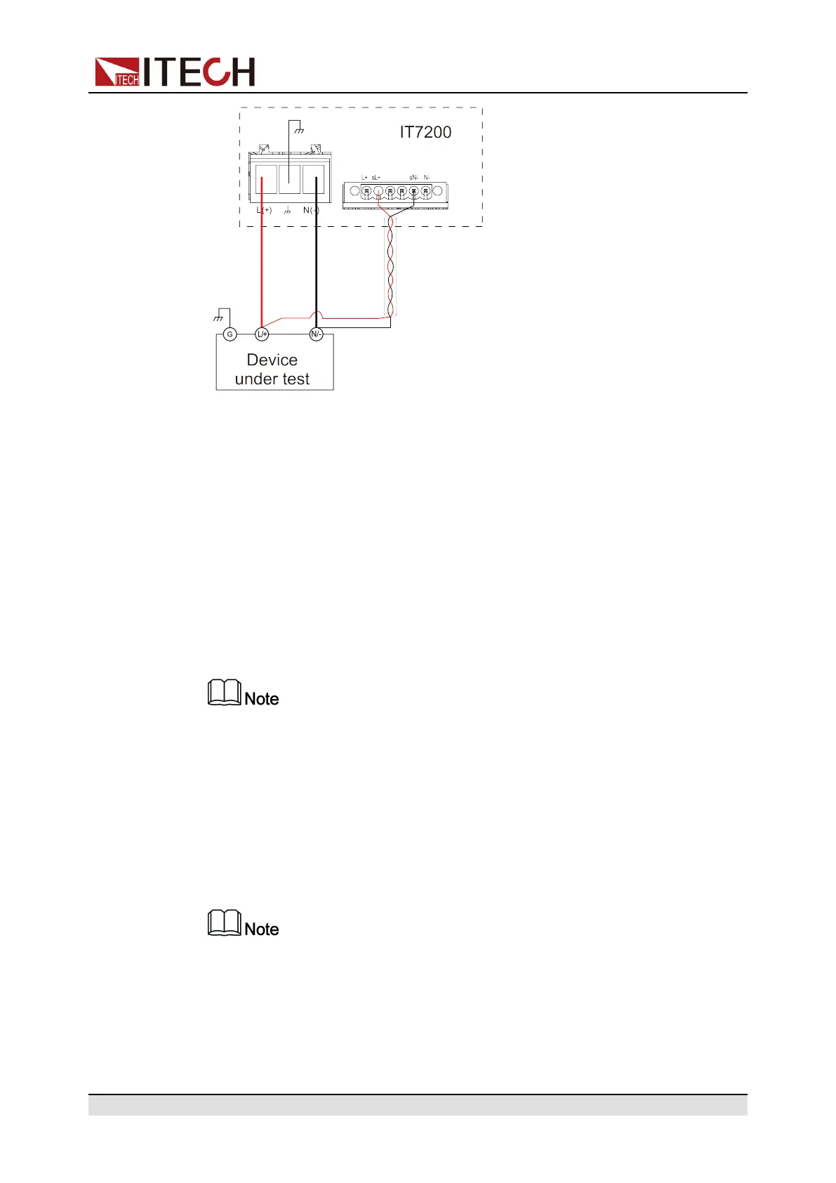
Inspection and Installation
1. Confirm that the power switch is in the Off position
2. Remove the cover of output terminal and remote sense terminal.
3. Disconnect the wires/short clips between sL+ and L+, sN- and N-.
4. Use armored twisted-pair cables to connect the remote sense terminals and
the device under test.
5. Loosen the screws of the output terminals and connect the red and black
test cables to the output terminals, and connect the ground terminal cor-
rectly. Re-tighten the screws.
6. Install the terminal cover, leave the other end of remote sense cables and
the red and black cables outside.
7. Connect the other end of the remote sense cables and the red and black ca-
bles to the DUT.
Test lines and sense lines should be as short as possible, and sense lines
should be twisted together.
2.6 Connecting the Interface
This series instrument comes standard with two communication interfaces:
USB, LAN, you can choose one of them to communicate with your computer.
When you use the remote interface to send SCPI instructions, if you use the
programming commands that involve modifying the instrument settings, such
as modifying the output voltage value, after completing the communication
connection between the instrument and the host computer, and after the
communication settings are completed, you must execute the SYST:REM
command firstly.
Copyright © Itech Electronic Co., Ltd.
20