Function and Features
Copyright © ITECH Electronic Co., Ltd. 45
On Recall Edit
2. Select edited files and press [Enter] for confirmation.
Recall List File=1
3. Operate Left/Right key and move to On. Press [Enter] key (The Trig lamp
that indicates VFD screen status is on). Press [Esc] key to exit setting.
LIST
On Recall Edit
4. Press [On/Off] key to open input and press [Trig] key (Triggering key)
List operation running.
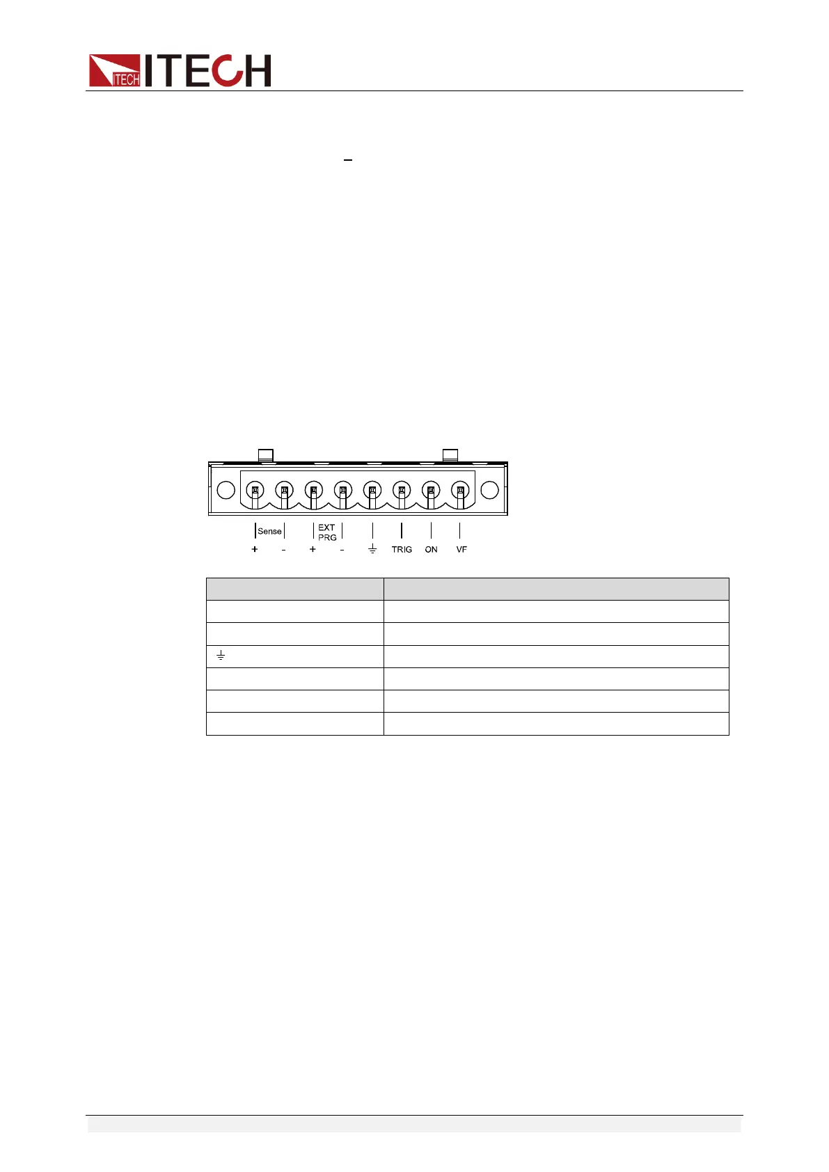
3.19 Terminal function of rear board
Terminals on IT8800 rear board comprise remote sensor terminal, external
trigger terminal, external analog control terminal, voltage fault indication
terminal, external On/Off control terminal and current monitoring terminal.
Terminal schematic (as shown below):
Pin Pin function
Sense+, Sense- Remote sense terminal
EXT PRG+, EXT PRG- External analog control terminal
Negative input terminal for TRIG, ON and VF
TRIG Positive input terminal for trigger
ON Positive input terminal for external On/Off control
VF Positive input terminal for voltage fault indication
3.19.1 Remote sense compensation functions
Under CC, CV, CR or CW mode, if the load consumes large current, a large
voltage drop will be detected in connection line between tested instrument and
load terminal. To ensure measurement accuracy, a remote sense measurement
terminal is provided at load rear board to compensate voltage drop lost in wire.
Remote sense operation: SENSE (+) and SENSE (-) are remote input
terminals. To avoid voltage drop caused by long input wire of load, the remote
sense allows direct measurement at input terminal source so as to improve
measurement accuracy.
Before using the remote sense measurement function, the user must set the
load in remote sense measurement mode.
Setting procedures:
Press [Shift] + 6 to enter menu. Move Left/Right key and select Remote-Sense.
Press [Enter] key and select ON to start Sense function.