30
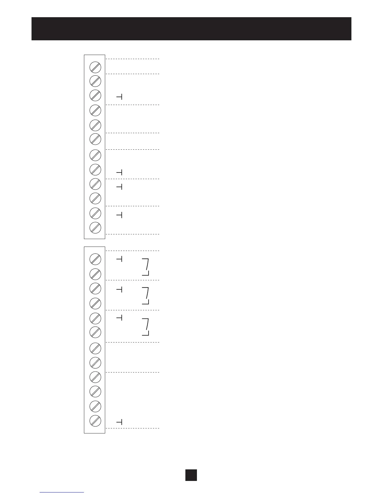
Electrical Installation and Wiring
Additional power supply ** max. 100 mA
Current signal input (required val. 2) 0-20mA / 4-20mA [Ri=50Ω]
To determine the required value or the offset
Analogue output 2 4-20mA
Analogue output 1 0-10 VDC
Current signal input (required val. 1) 0-20mA / 4-20mA [Ri=50Ω]
To determine the required value or the offset
Voltage signal input (required value 2) 0-10 VDC *DIG 4
To determine the required value or the offset
Voltage signal input (required value 1) 0-10 VDC
To determine the required value or the offset
Low water
incoming pressure switch or water level switch required (or jumper)
Configurable digital input 1 DIG 1
for switching between 2 required values or sensors
External ON/OFF (E-Stop) (Connect through switch or jumper)
Actual-value-voltage input sensor 1 0-10 VDC *DIG 2
Actual-value-voltage input sensor 2 0-10 VDC *DIG 3
Actual-value-current input sensor 2 0-20mA / 4-20mA [Ri=50Ω]
Sensor supply voltage ** maximum 100 mA
Actual value current input sensor 1 0-20mA / 4-20mA [Ri=50Ω]
Ground
* Terminals X3/5 and 6 can be used as actual value voltage input and also as digital input. Also the voltage
signal input on terminal X3/15 can be used as digital input.
** X3/3 and X3/24 → Σ maximum 100mA
X3X3
24 +24V
23
22
21
20
19 +10V
18
17
16
15
14
13
12
11
10
9
8
7
6
5
4
3 +24V
2
1