31
Electrical Installation and Wiring
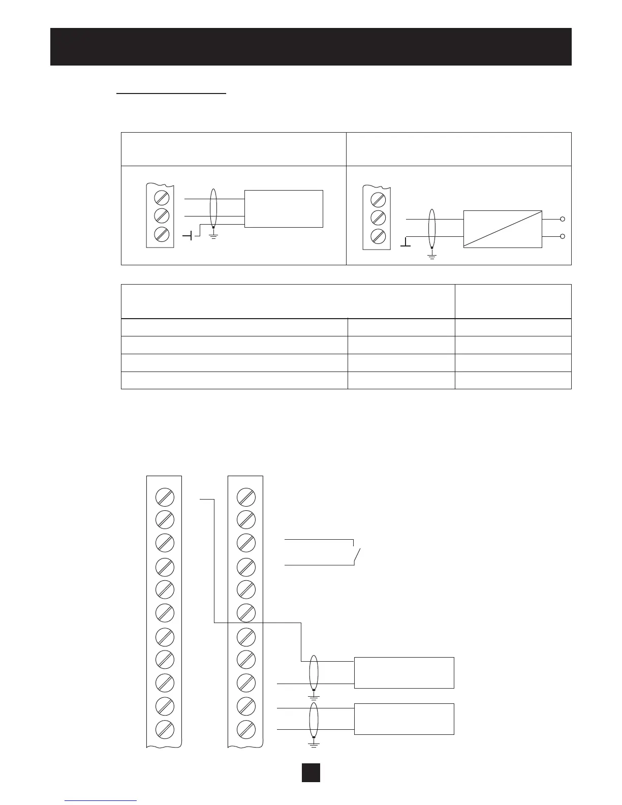
Connection Examples:
• Sensor–Actual-value-signal Input
Connecting a 3-wire transducer
Connecting an active actual-value-signal
(e.g. standard pressure transducer)
Possible Connections: Standard Pressure
Transducer:
Actual-value-signal input 0/4-20mA X3/4 … Sensor 2
+24VDC sensor supply X3/3 brown
Actual-value-signal input 0/4-20mA X3/2 … Sensor 1 white
Ground X3/1 screen / shield
• Switching between two individual sensors
External switching between two sensors by closing digital input 1 (X3/9-10). How to program
see SUBMENU SENSORS [0400].
X3
X3
3
2
1
4-20mA
4-20mA
~
3
2
1
X3
X3
24
23
22
21
20
19
18
17
16
15
14
12
11
10
9
8
7
6
5
4
3
2
Sensor 1
4-20mA
Sensor 2
4-20mA
Digital Input 1