32
}
}
Electrical Installation and Wiring
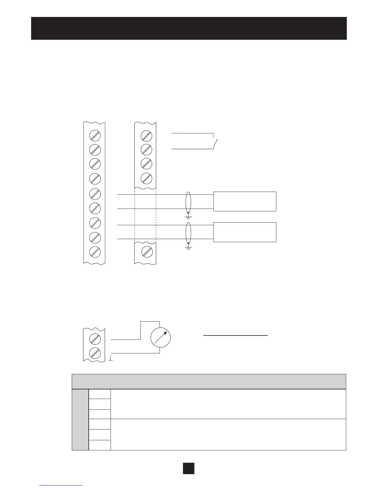
• Switching between two different required values
External switching between two connected required value signals (e.g.: between voltage and
current signal input) by closing digital input 1 (X3/9-10).
In ACTUATOR mode the drive can switch between two different frequencies from the digital
inputs. The input signals (current or voltage) will be proportional to the frequency.
(For programming see SUBMENU REQUIRED VALUES [0800].)
• Actual value – Frequency Indicator
e.g. to display the actual motor frequency
How to program see SUBMENU OUTPUTS [0700].
Possible connections:
Analogue output 1 (0-10V): X3/20
Analogue output 2 (4-20mA): X3/21
X4 RS485-Interface
X4/ 1 User SIO-Interface: SIO-
User interface
2 User SIO-Interface: SIO+
for external communication
3 GND, electronic ground
4 Internal SIO-Interface: SIO-
Internal interface between Hydrovars
5 Internal SIO-Interface: SIO+
for multi-pump systems
6 GND, electronic ground
X3
X3
22
21
20
19
18
17
16
15
14
10
9
8
7
2
0 - 10V
0/4 - 20mA
Digital Input 1 (to switch between
required value 1 and
required value 2)
Required Value 1
- external current signal
Required Value 2
- external voltage signal
X3
20 or 21