2: Key Features & Components
○○○○○○○○○○○○○○○○○○○○○○○○○○○○○○○○○○○○○○○○○○○○○○○○○○
User’s Manual
2•13
○○○○○○○○○○○○○○○○○○○○○○○○○○○○○○○○○○○○○○○○○○○○○○○○○○
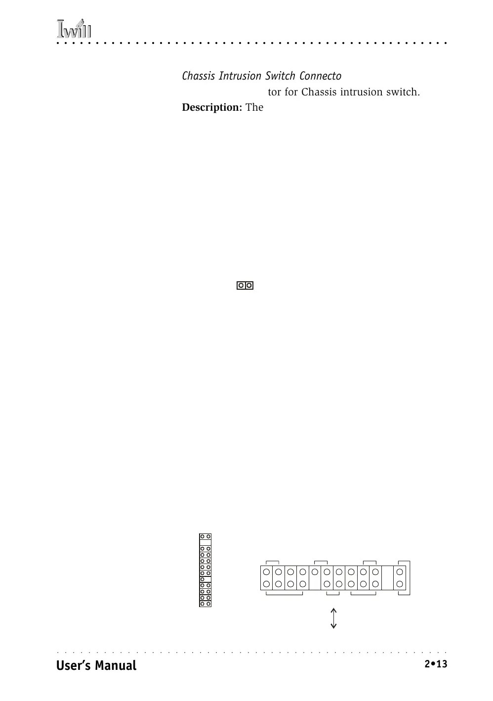
Chassis Intrusion Switch Connector
Function: Connector for Chassis intrusion switch.
Description: The hardware monitor subsystem supports
a chassis security feature that detects if the chassis (sys-
tem housing) cover is removed. When the cover is re-
moved, a signal is sent to the hardware monitor compo-
nent. The chassis intrusion circuit is powered by the sys-
tem power supply when the computer is connected to
AC power or by the onboard battery when it is not.
This feature uses a mechanical switch on the chassis that
connects to the chassis intrusion connector on the
motherboard. When the chassis cover is removed the
motherboard circuitry will detect the intrusion.
More Information: See the “System Features” section in
Chapter 6.
Front Panel Connectors
Function: Multifunction pin header connector for sys-
tem housing front panel features.
Description: This connector supports the following front
panel features:
• Reset Switch
• IDE device activity LED
• System ACPI Suspend switch
• System Power LED
• Keyboard lock
• Housing-mounted speaker
More Information: See Chapter 4 “Installing the Board
In A System Housing” and Chapter 6, “System Features”.
Chassis Intrusion Switch connector
Chassis Intrusion:
This 2-pin connector con-
nects to the lead from a
chassis-mounted chassis
intrusion switch.
Front Panel feature connector
Front Panel Connector:
Leads from the front panel
features connect to this
header.
System LED
Keyboard Lock
Power On
Speaker
IDE LED ACPIReset
KL