2: Key Features & Components
○○○○○○○○○○○○○○○○○○○○○○○○○○○○○○○○○○○○○○○○○○○○○○○○○○
User’s Manual
2•15
○○○○○○○○○○○○○○○○○○○○○○○○○○○○○○○○○○○○○○○○○○○○○○○○○○
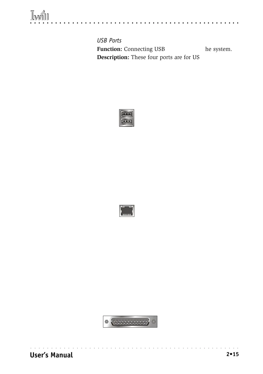
USB Ports
Function: Connecting USB 1.1 devices to the system.
Description: These four ports are for USB devices. Each
pair of ports is controlled by a separate USB root hub.
The ports are for “Type A” USB cable connectors. You
can connect or disconnect USB cables when the system
is turned on.
More Information: See the Integrated Peripherals sec-
tion of “Configuring the CMOS Setup Utility” in Chapter
5 for information on adjusting port settings.
LAN Port
Function: Connecting a CAT 5 LAN cable to the system.
Description: This is an RJ-45 connector for standard Cat
5 LAN cabling with RJ-45 jacks. The connector is for the
onboard LAN controller. You can connect or disconnect
a LAN cable when the system is turned on.
More Information: See the System Features section of
Chapter 6 for information LED modes.
Parallel Port
Function: Connecting a device with a parallel interface
to the system.
Description: The parallel port is generally used to con-
nect a printer to the system. The port supports common
parallel port modes and allows bidirectional communi-
cation. Use an IEEE 1284 compliant cable with the de-
fault ECP mode configuration.
More Information: See the Integrated Peripherals sec-
tion of “Configuring the CMOS Setup Utility” in Chapter
5 for information on adjusting port settings.
USB ports are paired 1/2, 3/4
USB Ports:
There are four USB ports.
Each pair of ports has its
own Host Controller and
Root Hub.
RJ-45 LAN jack
(on top of USB3, 4 ports)
LAN RJ-45 Jack:
Left-hand LED = Activity
Right-hand LED = Link
Front Panel feature connector
Parallel port:
The default mode is ECP,
configured as EPP 1.9,
DMA 3. 1284 compliant.