07610-003-60-98-L
59
PARTS
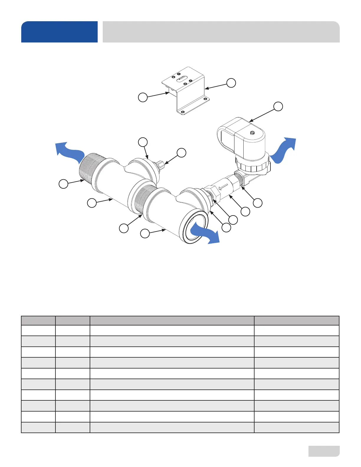
DRAIN WATER TEMPERING SYSTEM
ITEM QTY DESCRIPTION PART NUMBER
1 1 Thermostat 05930-003-13-65
2 1 Thermostat Bracket 05700-011-81-64
3 1 Solenoid Valve 04810-100-12-18
4 2 Nipple, Close Brass, 1/2” 04730-207-15-00
5 1 Valve, Check, 1/2” 04820-002-55-77
6 1 Reducer, 1 1/2” to 1/2” 04730-002-55-75
7 2 Tee, 1 1/2” x 1 1/2” x 1 1/2” 04730-011-69-93
8 2 Nipple, Close Brass, 1 1/2” 04730-207-40-00
9 1 Reducer, 1 1/2” to 1/4” 04730-002-55-76
10 1 Modied Compression Fitting 05700-001-16-52
Complete Drain Water Tempering System
05700-002-44-07
From the existing drain, attach the two additional Tees (Item 7) using the 1 1/2” Close Brass Nipples (Item 8). Tighten the
Reducers (Items 6 and 9) into the Tees as shown above. Attach the Modied Compression Fitting (Item 10) into the 1 1/2”
to 1/4” Reducer (Item 9). Position the bulb of the thermostat (Item 1) so that it rests approximately 1/4” from the bottom of
the Tee (Item 7). Tighten the Modied Compression Fitting (Item 10) as required.
Mount the Thermostat (Item 1) to the tub using the Thermostat Bracket (Item 2) and set it for 120–140 °F. Install the
Solenoid Valve (Item 3) to the second Tee (Item 7) and then attach to the incoming cold water line. Use thread tape as
required to prevent any leaks.
To Machine Drain
To Facility Drain
To Cold
Water Supply
10
2
3
1
9
4
5
4
6
8
7
8
7
 Loading...
