5-28 4181384 First Edition
HYDROSTATIC POWER TRAIN
5
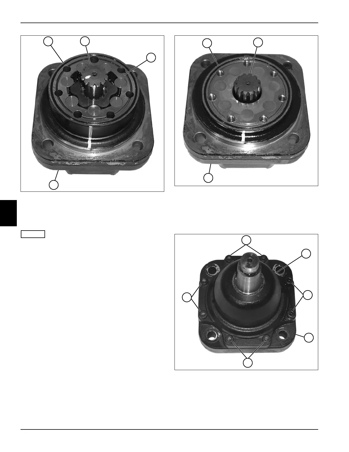
Figure 5-35
7. Remove the O-ring (13) from the gear wheel set (15).
8. Remove the valve drive (14) from the gear wheel set
(15).
NOTES
• The gear wheel set components are loose and can
fall apart when removed. When removing use caution
and remove the gear wheel set as a unit.
• Do not disassemble the gear wheel set. If
replacement is necessary, replace the entire
assembly.
9. Remove the gear wheel set (15) from the mounting
flange/bearing housing assembly (16).
Figure 5-36
10. Remove the O-ring (17) from the mounting flange
assembly (19).
11. Remove the drive shaft (18) from the mounting flange
assembly (19).
Figure 5-37
12. Remove eight socket-head screws (20) and remove
the bearing housing assembly (21) from the
mounting flange assembly (22).
TN1313
13
~
15
14
16
TN1314
17
18
19
TN1315
20
20
20
20
21
22