HYDROSTATIC POWER TRAIN
4181384 First Edition 5-29
5
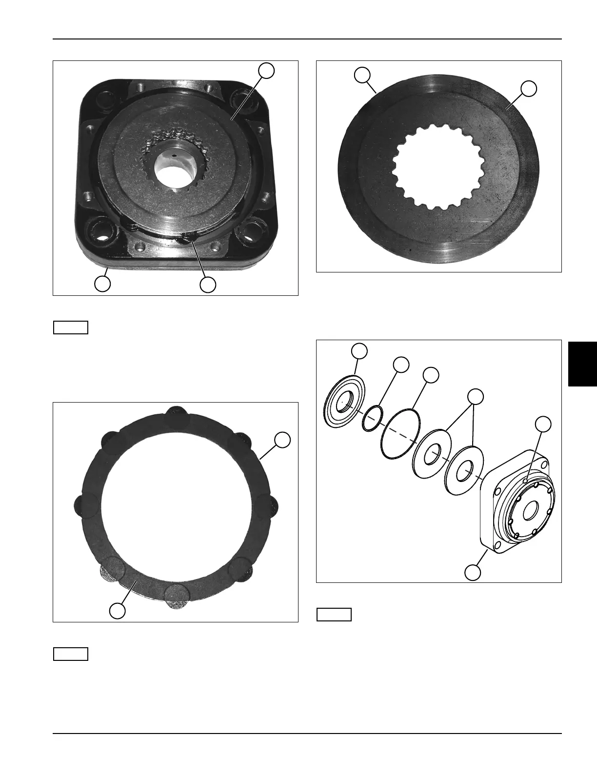
Figure 5-38
NOTE
Record the order of brake disks and stator rings to
ensure correct assembly.
13. Remove five brake disks (23) and six stator rings (24)
from the mounting flange assembly (25).
Figure 5-39
NOTE
Always replace the stator rings and brake discs as a set.
14. Inspect the friction surfaces (27) (front and rear).
Replace the stator rings (26) if the surfaces are worn
or damaged, or if any other damage is noted.
Figure 5-40
15. Inspect the disks for any scratches on the mating
surfaces (29) (front and rear). Replace the disks (28)
if any damage is noted.
Figure 5-41
NOTE
Record the orientation of the brake piston (30) and spring
discs (33) before removing to ensure correct installation.
16. Apply compressed air to vent (34), and remove the
brake piston (30), O-rings (31 and 32), and two
spring disks (33) from the mounting flange (35).
TN1316
23
24
25
TN1319
26
27
~
TN1320
28
~
29
TN1339
35
33
34
30
31
32