5-42 4181384 First Edition
HYDROSTATIC POWER TRAIN
5
IMPORTANT
The motor must be timed correctly.
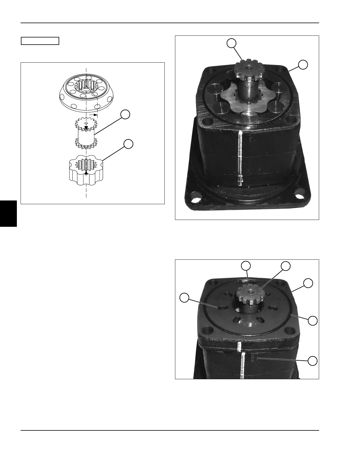
Figure 5-79: Correct Motor Timing
11. Mark the gear wheel set rotor (18) at the point where
the bottom of a spline tooth is opposite to the bottom
of a tooth in the external rotor teeth.
12. Mark the tip of a spline on both ends of the valve
drive (17).
13. Line up mark on gear wheel set rotor (18) with mark
on thinner gear face of valve drive (17).
Figure 5-80
14. Install the valve drive (17) in the gear wheel set (19)
positioning the thinner gear face toward the gear
wheel set.
Figure 5-81
15. Install the channel plate (23) over the valve drive
(22), positioning the oval ports (20) facing away from
the gear wheel set (25), and aligning the port (21) on
the channel plate with the port on the gear wheel set.
TN1367
~
17
18
19
17
TN1297
TN1297
23
21
22
20
24
~
25