HYDROSTATIC POWER TRAIN
4181384 First Edition 5-43
5
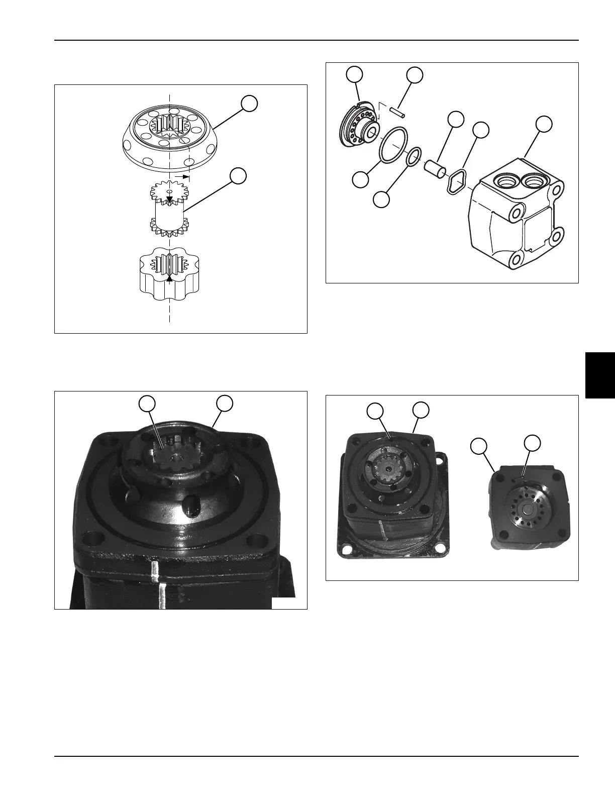
16. Install a new O-ring (24) on the channel plate (23).
Figure 5-82: Correct Motor Timing
17. Align mark on valve drive (27) with a hole in the outer
rim of disk valve (26).
Figure 5-83
18. Install the disk valve (26) over the valve drive (27).
Figure 5-84
19. Install alignment pin (29) in valve housing
(if removed).
20. Install new O-rings (33 and 34) on the balance plate
(28).
21. Install balance plate (28), spacer (30), and spring
washer (31) in the valve housing (32).
Figure 5-85
22. Install the valve housing assembly (37) on the
channel plate (36) aligning the port (38) on the valve
housing with the port (35) on the channel plate.
TN1367
~
27
26
TN1300
27
26
TN1305
29
28
30
31
32
33
34
TN1295
37
36
38
35