8-40 4181384 First Edition
CUTTING UNITS
8
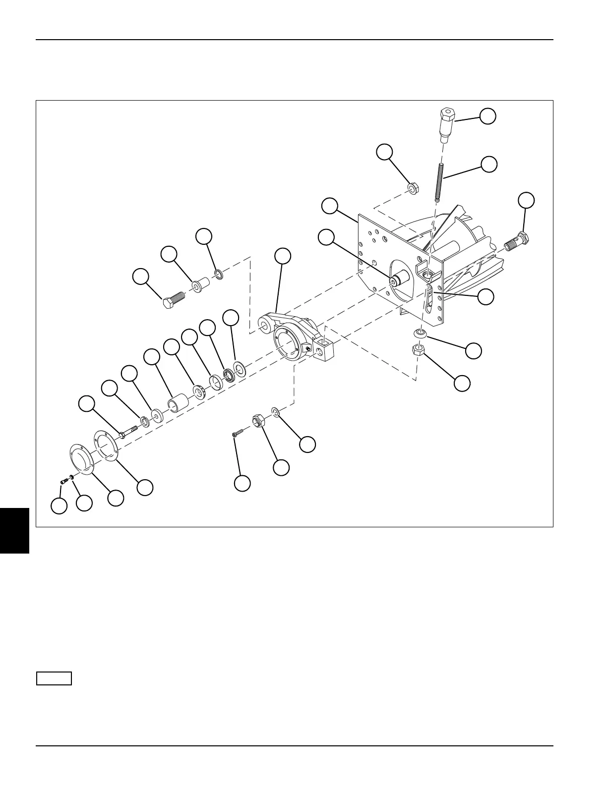
Removal and Installation—Non-Drive Side
See Figure 8-35.
Figure 8-35
1. Park the mower safely. (See “Park Mower Safely” on
page 1-7.)
2. Remove the yoke assembly and mounting bracket.
(See “Yoke Assembly” on page 8-45.)
3. Remove four screws (20) and lock washers (19), and
remove cover (18) and gasket (17) from the bearing
housing (4).
4. Remove screw (21), lock washer (22), bearing
retainer (23), and spacer (24) from reel shaft (5).
NOTE
Do not remove bearing cone (26) unless it is necessary
to replace the bearing (25). Always replace the bearing
and bearing cone as a set.
5. Remove bearing (25) from bearing housing (4).
6. Remove socket-head screw (16) from shoulder bolt
(10).
7. Remove the hex stover lock nut (13) and washer (12)
from adjusting screw (9).
8. Remove (unscrew) adjusting nut (8) from adjusting
screw (9).
9. Remove (unscrew) the adjusting screw (9) from the
shoulder bolt (10).
10. Remove lock nut (15) and washer (14) from shoulder
bolt (10).
TN1270
1
20
8
2
3
4
5
6
7
9
10
12
13
14
15
16
17
18
19
21
22
23
24
25
27
28
11
26