ACCESSORIES AND MISCELLANEOUS REPAIR
4181384 First Edition 9-9
9
Disassembly and Assembly
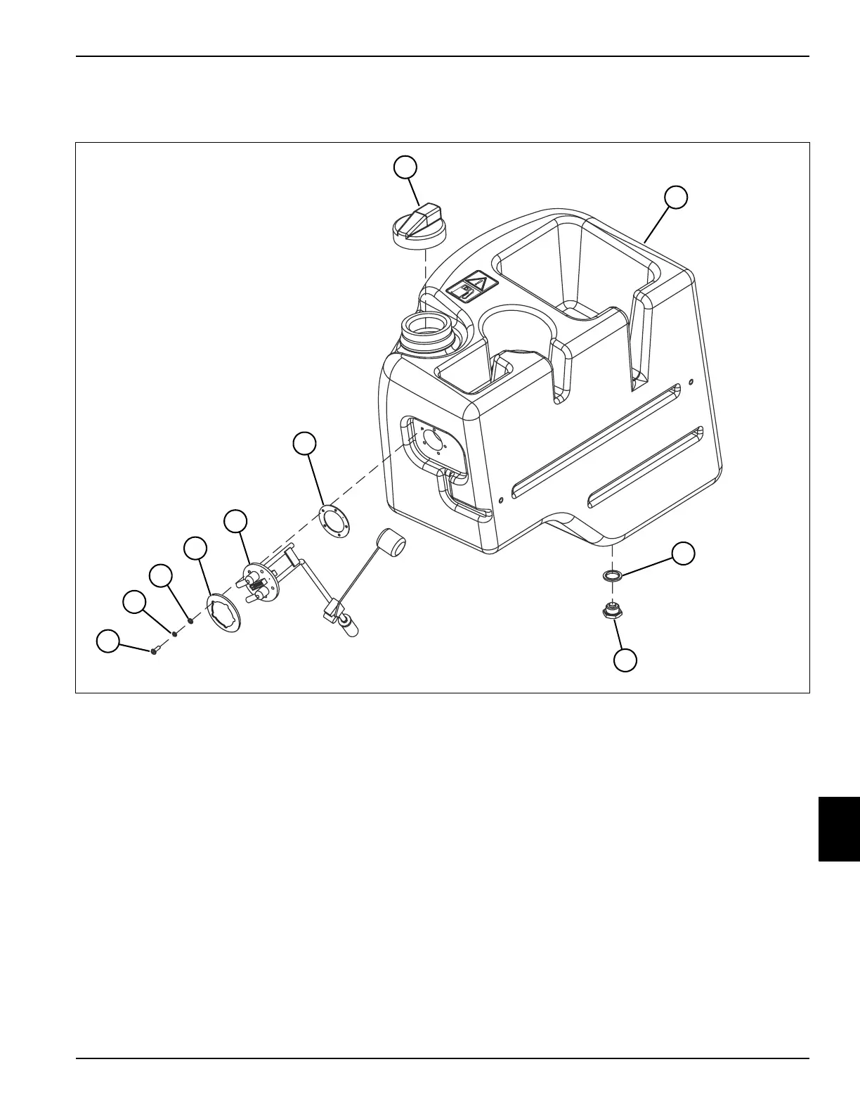
See Figure 9-17.
Figure 9-17
Disassembly Notes
• Record the orientation of the fuel sender (9), gasket
(10), and collar (8) before removing to ensure correct
installation.
• Inspect fuel tank (2) for wear or damage. Replace as
needed.
Assembly Notes
• Install new gasket (10).
• Install new O-ring (3).
1 Filler Cap
2 Fuel Tank
3O-Ring
4Drain Plug
5 Pan-Head Screw (5)
6 Lock Washer (5)
7Flat Washer (5)
8 Collar, Fuel Sender
9 Fuel Sender
10 Gasket
3
6
7
TN1025
1
9
10
4
2
5
8