9-14 4181384 First Edition
ACCESSORIES AND MISCELLANEOUS REPAIR
9
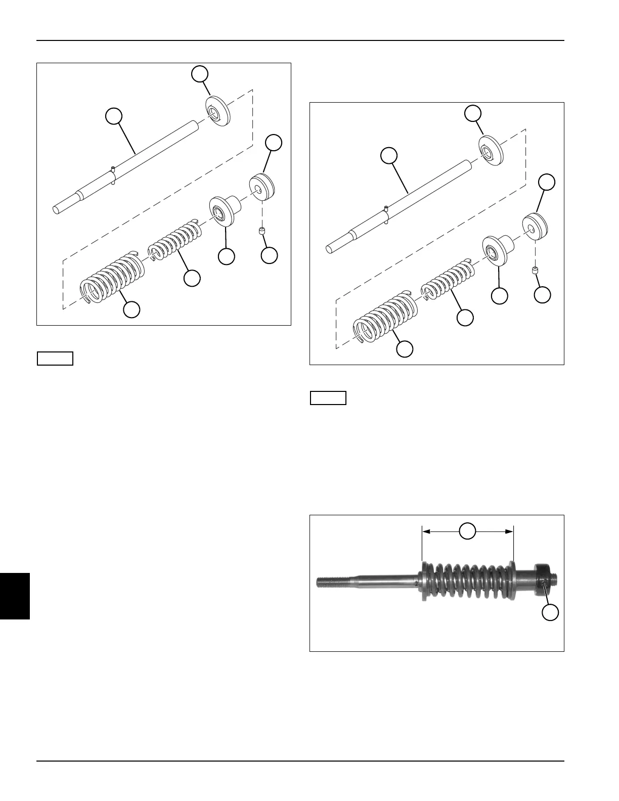
Figure 9-31
NOTE
Record the orientation of the reaction sleeves before
removing to ensure correct installation.
7. Loosen the set screw (13) and remove the piston
(12), reaction sleeve (14), inner (15) and outer (16)
springs, and reaction sleeve (11) from the piston rod
(10).
Assembly
See Figures 9-32 through 9-39.
Figure 9-32
NOTE
Install the reaction sleeves in the same orientation as
recorded during removal.
1. Install the reaction sleeve (2), inner (6) and outer (7)
springs, reaction sleeve (5), and piston (3) on the
piston rod (1).
2. Install, but do not tighten the set screw (4) to the
piston rod (1).
Figure 9-33
3. Loosen the set screw (9) and adjust the piston until
the distance (8) between the outside flanges of the
reaction sleeves is 2.75 inches (70 mm).
4. Tighten the set screw (9).
TN1108
14
12
13
15
16
11
10
TN1108
5
3
4
6
7
2
1
TN1116
9
8