39
UMG 509
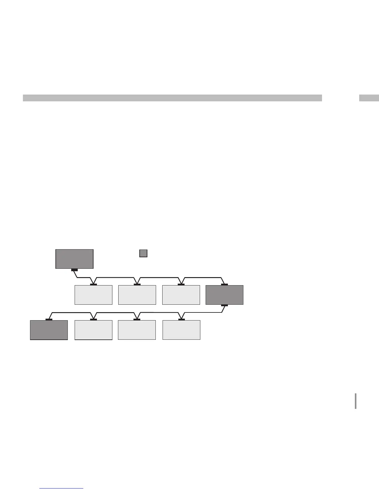
Bus structure
• All devices are connected in a bus structure (line)
and each device has its own address within the bus
(see also Parameter programming).
• Up to 32 subscribers can be connected together
in a single segment.
• The cable is terminated with resistors (bus termination
120 Ohm, 1/4W) at the beginning and at the end
of a segment.
• With more than 32 subscribers, repeaters (amplifiers)
must be used to connect the individual segments.
• Devices for which the bus connection is switched
on must be under current.
• It is recommended that the master be placed
at the end of a segment.
• If the master is replaced with a bus connection,
the bus must be switched off.
• Replacing a slave with a bus connection that is either
switched on or de-energised can destabilise the bus.
• Devices that are not connected to the bus can
be replaced without destabilising the bus.
Fig. Bus structure
SlaveSlaveSlave
Slave Slave Slave Repeater
Slave Slave Slave Slave
Master
Speisung notwendig / power supply necessary
Busabschluß eingeschaltet / bus terminator on
T
T
T
T
T

 Loading...