Do you have a question about the Jasco CD-1595 and is the answer not in the manual?
Explains instruction manual symbol, WARNING, CAUTION, and Note definitions.
Details labels attached to the instrument and their importance for safety.
Outlines software prohibitions, manual changes, copyright, and liability limitations.
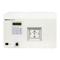
Introduces the CD-1595 detector and its applications in chiral separation analysis.
Lists technical specifications like light source, wavelength range, sensitivity, power, and dimensions.
Describes the front panel components, including the display, keypad, and controls.
Details the functions of the LCD display and the instrument's keypad for operation.
Explains the components and assembly of the flowcell for sample introduction.
Details the connectors, terminal blocks, parts, and labels on the rear panel.
Describes the automatic self-diagnostic checks performed upon instrument power-on.
Explains the procedure for safely powering down the instrument after operation.
Outlines the initial setup steps for connecting peripherals and the flow cell.
Guides on setting essential measurement parameters like wavelength, gain, and response.
Details the procedure for conducting a measurement after parameters are set and baseline is stable.
Lists and explains potential error messages that may appear during instrument operation.
Provides an overview of the instrument's operational functions accessed via the [SHIFT] key.
Explains how to configure the UV signal output settings for an external integrator.
Details optical zeroing and checking preamplifier output for accurate CD signal measurement.
Describes the function and setting of the lamp off timer to conserve lamp life.
Explains how to set the appropriate range for data output to the recorder.
Guides on selecting between AU REC OUT and G FACTOR OUT modes for recorder output.
Details adjusting the integrator output zero level to prevent signal clipping for negative peaks.
Shows how to check the lamp's total operating time for replacement estimation.
Explains how to change the output polarity for signals sent to the recorder.
Describes the different autozero modes (AUTO, MANUAL, HOLD) for baseline stabilization.
Explains how to monitor the calculated g factor in real time during operation.
Guides on setting the flowcell path length for accurate CD signal correction.
Overview of program mode capabilities for automated parameter changes over time.
Explains how to set and load program files into the instrument's memory.
Details how to transition between the normal and program modes of operation.
Covers the procedures for editing initial parameters and the time program sequence.
Explains how to run, stop, and modify parameters while a time program is active.
Introduces the spectrum measurement capabilities and limitations of the detector.
Explains the single-beam method, baseline correction, and spectrum acquisition process.
Summarizes the key operations for entering and navigating the SPECTRUM mode.
Details the steps for acquiring the baseline spectrum for spectral correction.
Guides on how to measure a sample's spectrum and store it in memory.
Explains how to output measured spectra to a recorder or integrator terminal.
Explains the optical diagram and the fundamental working principle of CD measurement.
| Brand | Jasco |
|---|---|
| Model | CD-1595 |
| Category | Security Sensors |
| Language | English |