5-4
CDRANGE:0.0001
AURANGE:0.0100
(GRANGE:1E‑5)
[SHIFT] [3]
Monitor screen
[EDIT/ENTER]
NORM291X10
0.0000.000STD
[ ][ ][EDIT/ENTER]
▲
▼
[MONITOR]
Blinking
[ ][ ][EDIT/ENTER]
▲
▼
CDRANGE:0.0001
AURANGE:0.0100
(GRANGE:1E‑5)
CDRANGE:0.0001
AURANGE:0.0100
(GRANGE:1E‑5)
Blinking
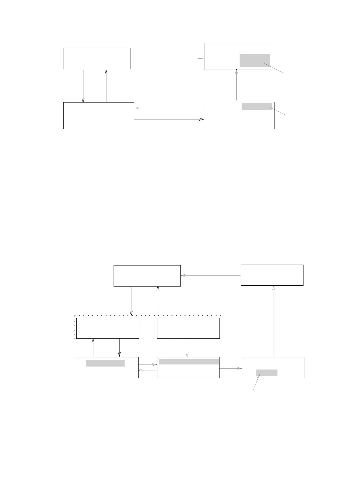
Figure 5. 5 Setting recorder range
Selectable range
CD RANGE: 0.0005〜1.28 Degree and S(Short) 13steps
AU RANGE: 0.001 〜 2.56 AU and S(Short) 13steps
G RANGE: 1E-5(1x10
-5
) 〜 2.56E-2(2.56x10
-2
) and S(Short) 13steps
5.6 [SHIFT] [4]: Selecting Recorder Output Mode
“AU REC OUT” or “G FACTOR OUT” mode can be selectable on this
function.
If “G FACTOR OUT” mode has been selected ,a signal CD/UV ( g factor) can
be outputted from the UV output terminal for recorder on the reae panel (see
Fig.4.1) in place of UV absorbance output.
[SHIFT] [4]
Monitorscreen
NORM 291 X10
0.0000 0.0000 STD
[MONITOR]
AU REC OUT
[EDIT/ENTER]
[MONITOR]
G FACTOR REC OUT
0.001 AU
[EDIT/ENTER]
or
AU REC OUT
G FACTOR REC OUT
G FACTOR REC OUT
0.001 AU
▲
[ ]
▼
[ ]
[EDIT/ENTER][EDIT/ENTER]
G FACTOR REC OUT
0.001 AU
[EDIT/ENTER]
[Numeric key]
Incasetheabsorbancevalueislessthanthevalue
settingathere,GFACTORalwaysoutputs0.00000.(Referto
「5.11」)Thisvalueissettablewithintherangeof0.0
〜1.000.
Figure 5.6 Selecting Recorder Output Mode
Artisan Technology Group - Quality Instrumentation ... Guaranteed | (888) 88-SOURCE | www.artisantg.com