30
5. Operation and maintenance devices
5. Operation and maintenance devices
5.1. Hydraulic system
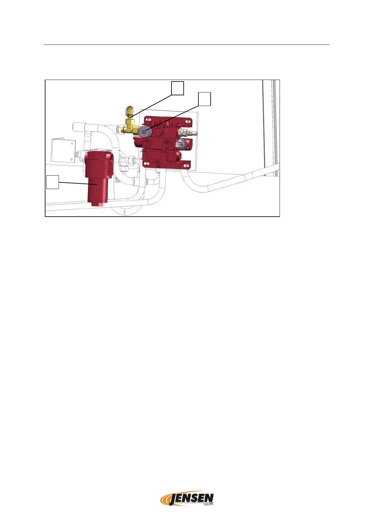
Hydraulic components on the side of the infeed chute, schematic display, differences in design and type possible.
5.1.1. Chip size adjustment
The chip size adjustment can be found on the side of the infeed chute.
The speed of the infeed is adjustable with the turning knob (1) of the hydraulic valve
manifold. The size of the chips can be manipulated by the speed of the infeed. The
chips become smaller by reducing the speed of the infeed.
The functional performance of the hydraulic oils depends on the temperature, because
of that it is possible that the chip size must be adjusted when conditions change.
5.1.2. Filter
Normally the hydraulic system is equipped with two filters.
The suction filter is located in the inlet line between hydraulic tank and hydraulic pump.
The pressure filter (2) is located in the pressure line between hydraulic pump and valve
manifold.
5.1.3. Measurement port
For measuring of the working pressure the measurement port (3) is located on the
pressure line.
1
2
3