M
Ingenieurbüro CAT, M. Zipperer GmbH +49-7634-5056-800
Wettelbrunner Straße 6 sales@jetcat.de
13 79282 Ballrechten-Dottingen www.jetcat.de
GERMANY
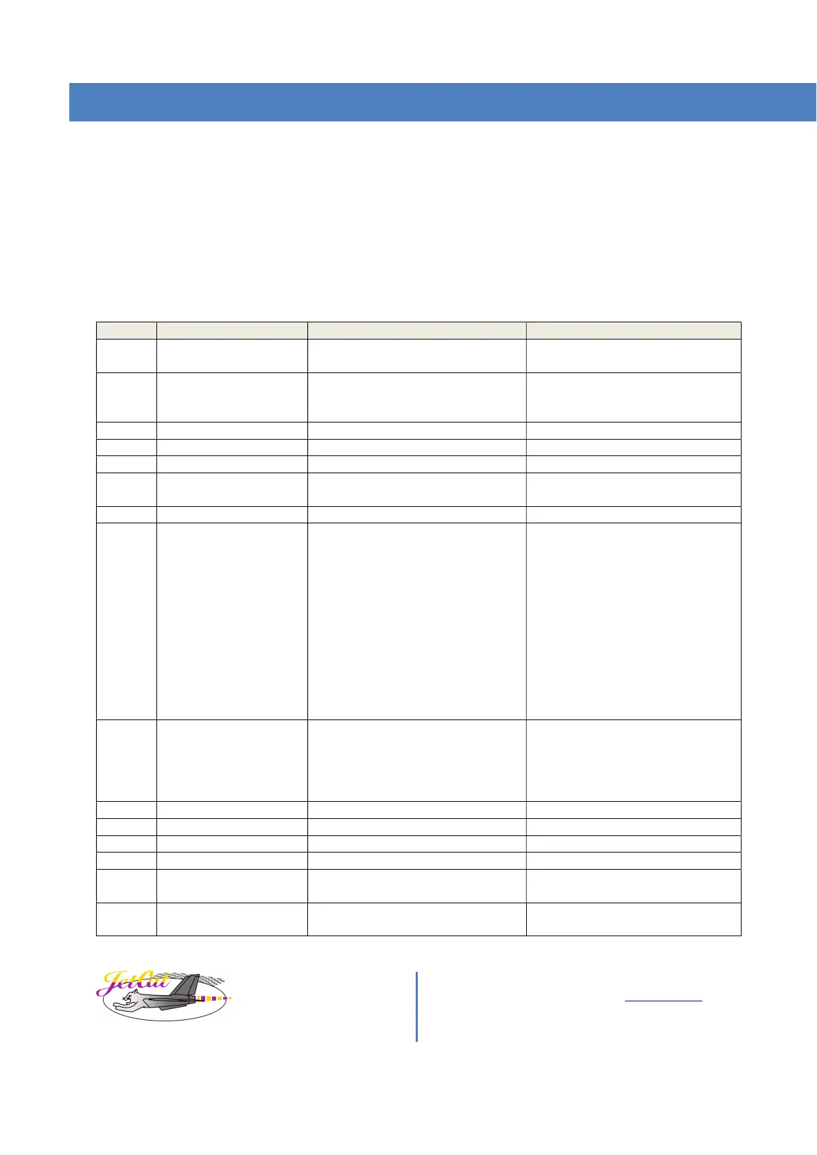
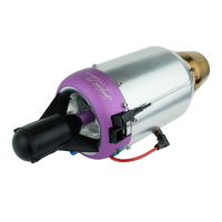
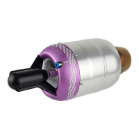
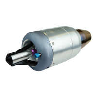
Data connector (A)
The data connector of the engines provides all necessary control signals for engine control as well as power on.
15pin SUB-D male connector
FCT - A MOLEX COMPANY FL, Sub-D Connector, 15-pin, straight, male
RS -No.: 812-6359
Pin-Inserts:
Sub-D-contact, Series: FK20PL, Male, Crimp, 24 → 20 AWG FK20PL-08V
RS -No.: 812-6220
Pin Description Info Suggested connection
1 GND Signal Ground Connect to ground/negative pole of
2 Throttle PWM input RC-PWM Signal (THR) Connect to servo PWM signal (0,8-
2,2ms) if throttle control should be
5 TXD 3,3V (COM1) Serial interface transmit line
6 RXD-Cross Check, COM2 Secondary serial interface receive
8 Safety Shutdown input /
engine “kill” signal.
Safety shut down input.
This is an input for additional flight
termination systems.
This input pin should not be used to
stop the engine under normal
conditions.
Needs to be connected to GND to
allow engine to run.
This signal is only present on P1000
engines or engines with ECU
hardware setup V2.0 or higher!
Connect this pin to GND to enable
internal valves and pump!
If left open, valves and pump are
disabled by septate hardware
circuitry! ( engine cannot run).
If disconnected during engine run,
engine will be shut down
immediately with GSU error
message: “Kill Sig”
9 Power On Signal (4-14V)
See note 1 below!
Apply a positive voltage to power up
ECU/engine
Connect to positive pole of power
supply, to switch on ECU/engine
system. If disconnected ECU is
turned off. See also page 29 Engine
Power ON/OFF
Serial interface receive line
13 +5V out, max 200mA +5V output to GSU
14 TXD-Cross Check, COM2 Secondary serial interface transmit
15 Airspeed 0-2,5V Airspeed Sensor or Analog