M
Ingenieurbüro CAT, M. Zipperer GmbH +49-7634-5056-800
Wettelbrunner Straße 6 sales@jetcat.de
31 79282 Ballrechten-Dottingen www.jetcat.de
GERMANY
Control via analog signal (0-3,3V) fed into Airspeed input
The ECU allows to use the analogue input, normally used for the airspeed sensor, to be used for the throttle control
signal.
For this special mode, the engines “Operation mode” needs to be set to one of the “Industrial” modes and the
parameter “THR-Ctrl Input” needs to be set to “Airspeed Signal”. Both settings can be found in the Limits menu. If set
like this, obviously the airspeed signal is no longer available.
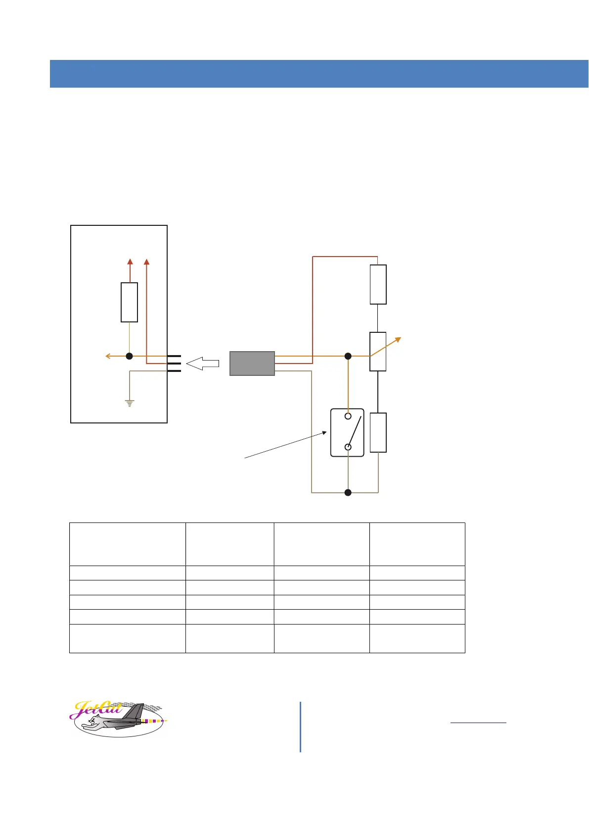
A suggested typical wiring of e.g. a potentiometer for engine thrust control to this input would then look like this:
10 kOhm
Potentiometer
to airspeed
sensor input
1,8 kOhm
Switch
(engine OFF
when closed)
10 kOhm
(+5V)
(GND)
+5V
ECU-internal
GND
220 kOhm
analog
input (0-3,3V)
+3.3V
Position
approx.. control
voltage
Right (max) position Closed Engine OFF 0V
Potentiometer/switch
circuitry disconnected
--- Error Off >3.13V treated as
error/failure
If the potentiometer circuitry should accidentally be disconnected to the analog input, the signal would internally be
pulled high (3,3V), allowing the ECU to detect this as a failure and shutting down the engine.