radio control system
EN
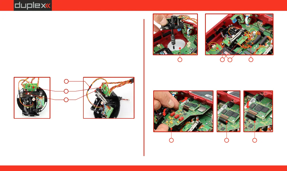
12. Slide the included heat shrink tubing over the cables and shrink
it according to the picture.
13. Solder the cables to the marked solder pads according to the
color coding (see the picture).
14. Move the gimbal to all extreme positions to define the length of
the cables in the movable part of the gimbal, and gently pull the
cable away from the gimbal. The cables should have sufficient
slack in the movable part of the gimbal to avoid contact with
moving parts and not be strained by bending.
15. Secure the cables in the heat shrink tubing at the designated
point of the gimbal (see the picture).
12
13
15
16. Reinsert the gimbal back into the transmitter.
17. Tighten both mounting screws of the gimbal.
18. Connect the cable connectors leading from the gimbal (4
connectors from one gimbal: and ). X, Y, SVM
19. Secure the gimbal cables back in the holders.
20. Insert the control circuit board (PCB) back into the transmitter
(a)(b) and gently press it into the connector .
21.(c)(d) Insert the display strip into the connector and secure it
(see the picture).
[
17
16
XXX
YYY
SSS
VMVMVM
18
19
(a)(a)(a)
(b)(b)(b)
(c)(c)(c)(d)(d)(d)
[
202121
67
www.modellmarkt24.ch



 To Next Page