25 of 76
7.4 INSTALLATION OF TOWERS
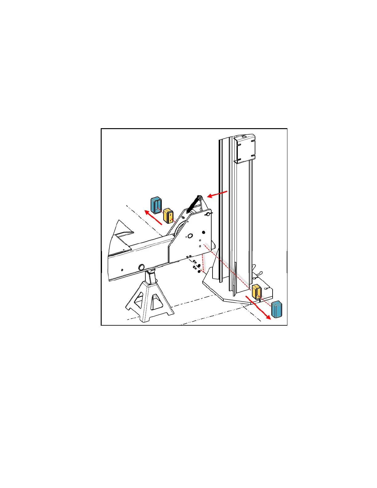
1. Remove the slider block weldments from both crossmembers by removing the
3/8”-16UNC x 1”LG Hex HD Bolts and 3/8” lock washers attaching them to the
crossmember. See Figure 16.
2. Determine which tower is the power post (see Figure 4) and position it in the
front left corner. Position the remaining three towers at the other corners of the
lift.
3. Slide each tower around the crossmember so that the holes for attaching the
slider blocks are roughly halfway inside the channel.
Figure 16. Tower Installation
4. Place the Glide Bearings (located in the accessory box) on the slider block
weldments and bolt the slider block weldments back onto the crossmember using
the 3/8”-16UNC x 1”LG Hex HD Bolts and 3/8” lock washers removed previously.
5. Pull the towers backwards (away from the decks) so that the slider blocks are
contacting the inside of the tower.
6. Repeat for remaining towers.