Engineering manual - SAB 193-233-283 S A-frame (including ATEX)
116/168
008831 en 2020.10
Installation instructions
Compressor units with oil separator OHU 04136
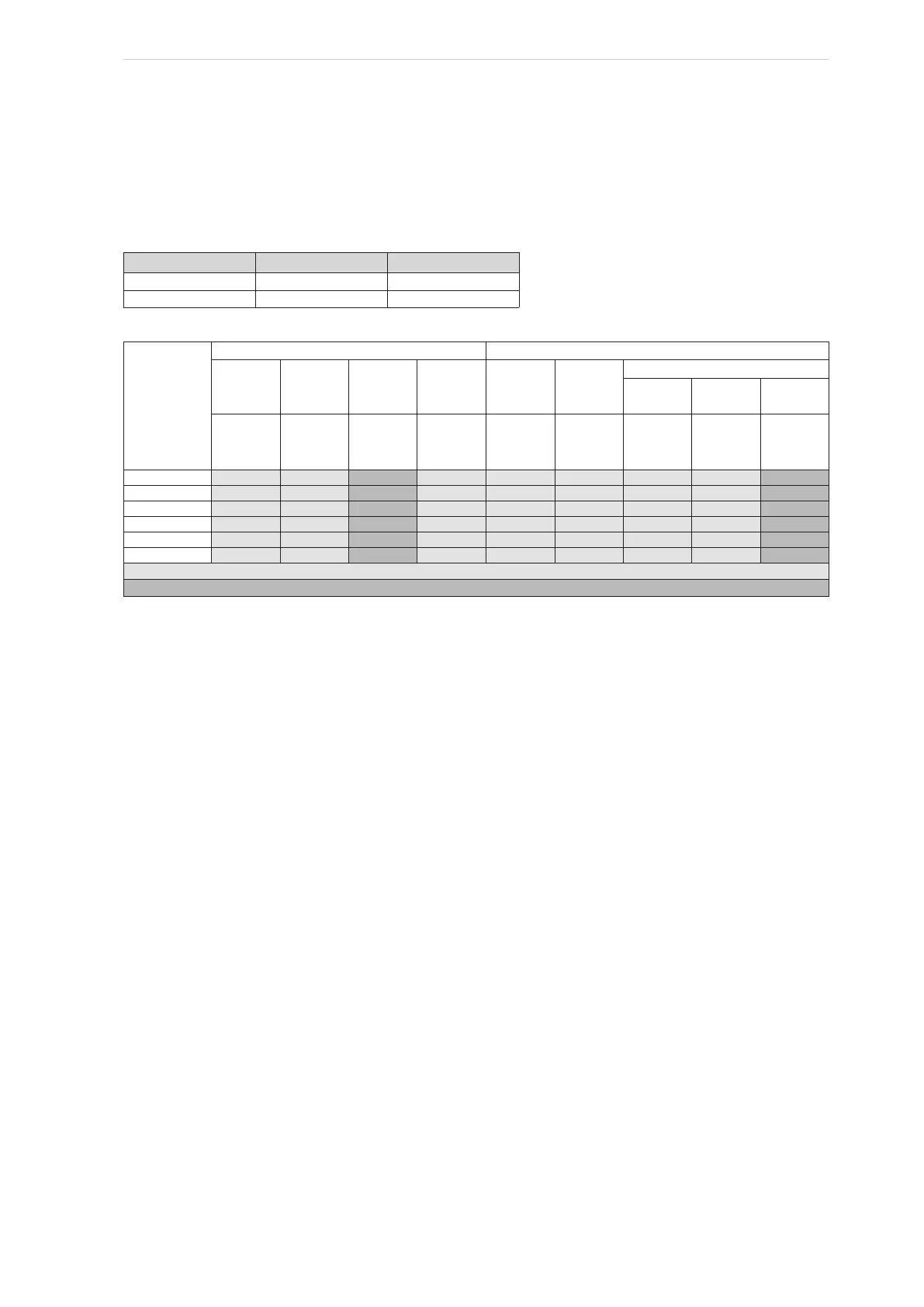
Note: Only calculations with separator OHU 04136 can be made using the data below.
Dimensions of oil separator OHU 04136
(l, b measured between "feet", h to the upper side of the horizontal profiles).
Length x Width y Height z
l b h
3419 1070 1187
Table 37
Motor displacement
Compressor
Column
1
Column
2
Column
3
Column
4
Column
5
Column
6
Centre of gravity on unit
Column
7
Column
8
Column
9
x
flange
Yg
motor
zg
motor
Shaft
height
∆z
zi
∑M
comp
X Y
z
SAB 283 S 1058 425 1574 387 406 2383 2060 532 1593
SAB 233 E 2393 444 1514 327 372 1703 2063 569 1559
SAB 233 L 1103 444 1514 327 362 1646 1949 544 1549
SAB 233 S 1103 444 1514 327 348 1510 1909 529 1535
SAB 193 S 1120 459 1477 290 310 1065 1956 545 1497
SAB 193 L 1120 459 1477 290 325 1190 1983 539 1512
Fixed values
Calculated and/or edited values
Table 38
∑M comp = comp + tunnel+ support + POV
zi: centre of gravity of compressor in relation to dist. flange
zg motor = h + Shaft height ∆z
z = h + zi
Shaft height ∆z: dist. discharge flanges (∆z) to drive shaft
zi from Table 38, Column 5
Example: SAB 233 L = gives
zg motor = 1187 + 327
z = 1187 + 362