Engineering manual - SAB 193-233-283 S A-frame (including ATEX)
76/168
008831 en 2020.10
Physical and connection data
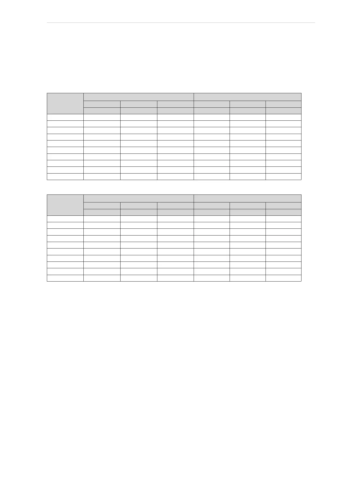
5.2 Allowable flange loads
In any screw compressor installation, suction and discharge lines should be supported in pipe
hangers (preferably within 2 ft of vertical pipe run) so that the lines will not move if disconnected
from the compressor, see Table 12 and Table 13.
Noz. size
Nps
Torque (ft-lbf) Torque {Nm]
Axial
Vert. Lat.
Axial
Vert. Lat.
M
R
M
C
M
L
M
R
M
C
M
L
1
25 25 25 34 34 34
1.25 25 25 25 34 34 34
1.5 50 40 40 68 54 54
2 100 70 70 136 95 95
3 250 175 175 339 237 237
4
400 200 200 542 271 271
5 425 400 400 576 542 542
6 1000 750 750 1356 1017 1017
8 1500 1000 1000 2034 1356 1356
10 1500 1200 1200 2034 1627 1627
Table 12: Allowable flange loads
Noz. size
Nps
Load (lbf) Load [N]
Axial
Vert. Lat.
Axial
Vert. Lat.
P V
C
V
L
P V
C
V
L
1 50 50 50 222 222 222
1.25 50 50 50 222 222 222
1.5 100 75 75 445 334 334
2 150 125 125 667 556 556
3 225 250 250 1001 1112 1112
4 300 400 400 1334 1779 1779
5 400 450 450 1779 2002 2002
6 650 650 650 2891 2891 2891
8 1500 900 900 6672 4003 4003
10 1500 1200 1200 6672 5338 5338
Table 13: Allowable flange loads