Engineering manual - SAB 193-233-283 S A-frame (including ATEX)
120/168
008831 en 2020.10
Installation instructions
7.26 Instruction for mounting of coupling
The arrangement of motor and compressor is mounted stress-free on the unit to ensure sound
operation. The arrangement is pre-aligned from factory. If the motor has not been mounted from
factory or if, for some other reason, either the motor or the compressor has been mounted on
site, the arrangement must be aligned properly by means of shimming and/or adjustment.
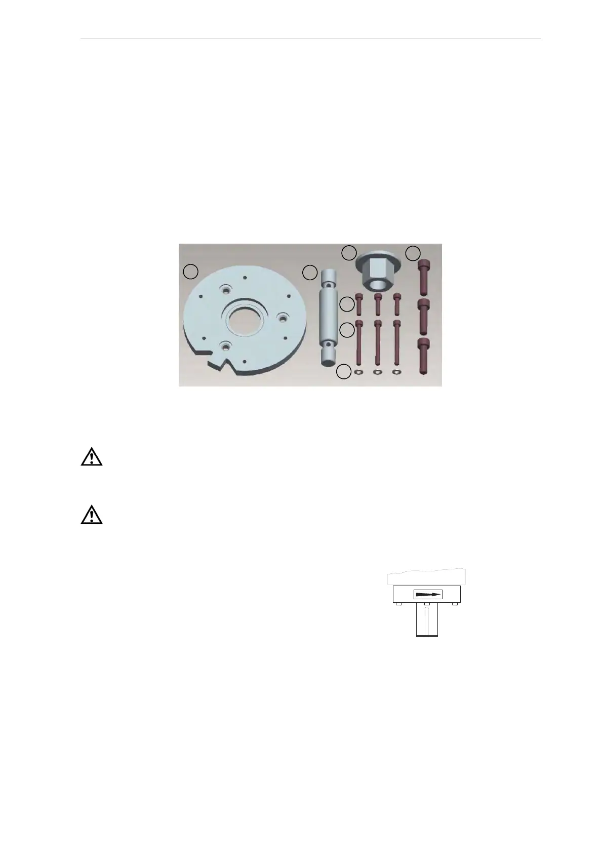
In order to be able to mount and dismantle the coupling, without the risk of damaging any compo-
nents such as the shafts or the coupling parts, a special toolset has been designed. The toolset
(part no. 3083-398) is shown in Fig. 82 and is available from the Johnson Controls Industrial Re-
frigeration Parts Centre in Denmark, if required. The use of the toolset is described in the “Com-
missioning guide, mechanical”.
Fig. 82
Checking motor/compressor rotation
Warning!
Make sure that the coupling hubs are tightened to the shaft before rotating the motor to prevent
them from flying off and possibly causing serious injury or death.
Warning!
Injury may occur if items such as loose clothing become entangled in the spinning motor shaft.
Compressor rotation is clockwise when
facing the end of the compressor shaft.
Under no conditions should the motor rotation
be checked with the coupling centre installed as
damage to the compressor may result. Bump
the motor to check for correct compressor rota-
tion. After verification, install disc drive spacer
as applicable.
Compressor/motor coupling installation
The unit has compressor to motor alignment through the use of a machined cast iron tunnel. This
tunnel is factory-set through machining tolerances ensuring motor/compressor alignment.
No alignment is required in the field. See Fig. 83.