Engineering manual - SAB 193-233-283 S A-frame (including ATEX)
008831 en 2020.10
65/168
Technical description
subcooling is provided by flashing liquid in the economiser cooler to an intermediate pressure
level. The intermediate pressure is provided by a port located part way down the compression
process on the screw compressor. As the screw compressor unloads, the economiser port will
drop in pressure level, eventually being fully open to suction. Because of this, an output from the
microprocessor is generally used to turn off the supply of flashing liquid on a shell and coil or DX
economiser when the capacity falls below approximately 45%-60% capacity (85%-90% slide
valve position). This is done because the compressor will be more efficient operating at a higher
slide valve position with the economiser turned off, than it will at a low slide valve position with
the economiser turned on. Please note, however, that shell and coil and DX economisers can be
used at low compressor capacities in cases where efficiency is not as important as assuring that
the liquid supply is subcooled. In such cases, the economiser liquid solenoid can be left open
whenever the compressor is running.
Due to the tendency of the port pressure to fall with decreasing compressor capacity, a back-pres-
sure regulator valve (BPR) is generally required on a flash economiser system (Fig. 49) in order to
maintain some preset pressure difference between the subcooled liquid in the flash vessel and
the evaporators. If the back-pressure regulator valve is not used on a flash economiser, it is possi-
ble that no pressure difference will exist to drive liquid from the flash vessel to the evaporators,
since the flash vessel pressure will approach suction pressure at a decreased slide valve position.
In cases where wide swings in pressure are anticipated in the flash economiser vessel, it may be
necessary to add an outlet pressure regulator to the flash vessel outlet to avoid overpressure of
the economiser port, which could result in motor overload. Example: A system feeding liquid to
the flash vessel in batches.
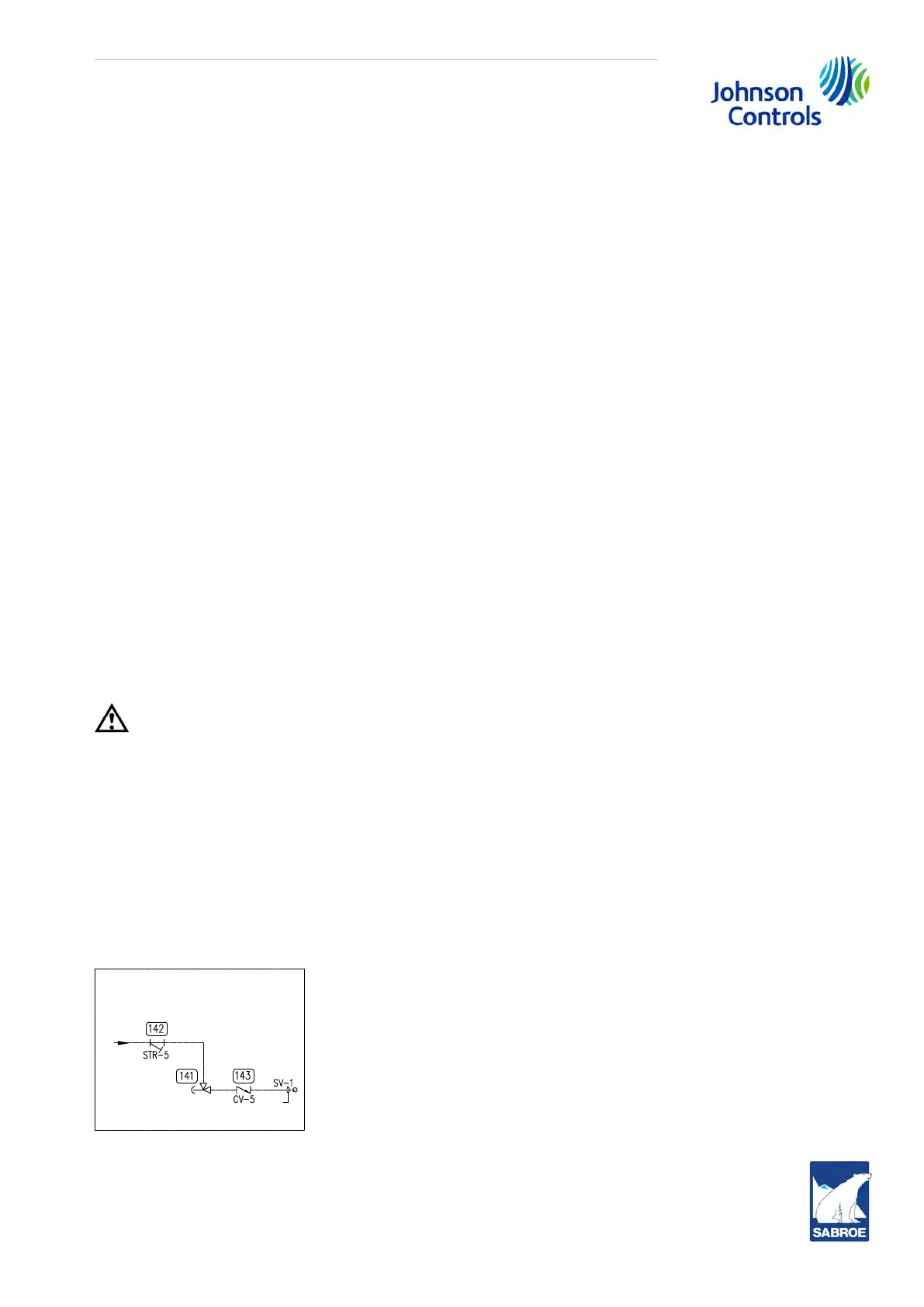
The recommended economiser systems are shown below. Notice that in all systems there should
be a strainer (STR) and a check valve (CV) between the economiser vessel and the economiser
port on the compressor. The strainer prevents dirt from passing into the compressor, and the
check valve prevents oil from flowing from the compressor unit to the economiser vessel during
shutdown.
Caution!
It is recommended to use piston-type check valves for installation in the economiser line, as op-
posed to disc-type check valves. The latter are more prone to gas pulsation-induced failure. The
isolation and check valves as well as the strainer should be located as closely as possible to the
compressor, preferably within 1 metre.
Anti-vibration kit
For SGC compressors running ammonia at high suction temperature and variable frequency drive
(VSD), an anti-vibration kit should be installed on the economiser line. The anti-vibration kit con-
sists of a strainer, a stop valve, a check valve and a damper (pos. 208). The damper should be in-
stalled as the last device before the compressor.
Fig. 44: Standard economiser kit