JOHNSON CONTROLS
121
SECTION 4 - PRINTERS
FORM 160.10-O1
ISSUE DATE: 4/27/2018
4
PRINTER CONNECTIONS
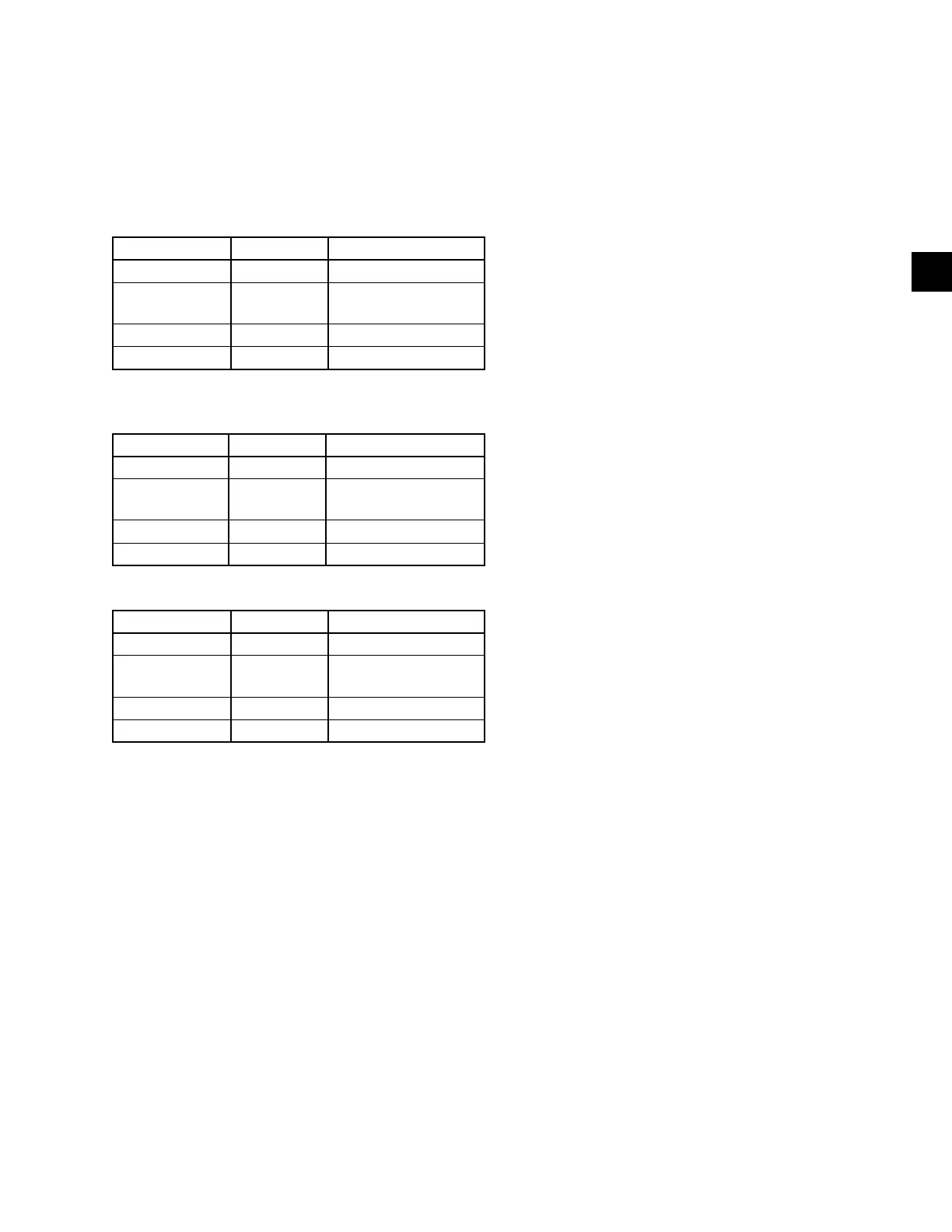
Connect the listed printers to the control center mi-
croboard as follows. Only one printer can be connected
at a time.
TABLE 10 - OKIDATA 182, 182 TURBO, 184 TURBO
PRINTER CONNECTIONS
MICROBOARD PRINTER FUNCTION
J2-4 pin 3 Tx (data to printer)
J2-2 pin 11
DSR (busy signal from
printer)
J2-9 pin 7 Gnd
Cabinet Shield
TABLE 11 - WEIGH-TRONIX PRINTER
CONNECTIONS
MICROBOARD PRINTER FUNCTION
J2-4 pin 2 Tx (data to printer)
J2-2 pin 5
DSR (busy signal from
printer)
J2-9 pin 7 Gnd
Cabinet Shield
TABLE 12 - SEIKO PRINTER CONNECTIONS
MICROBOARD PRINTER FUNCTION
J2-4 pin 3 Tx (data to printer)
J2-2 pin 8
DSR (busy signal from
printer)
J2-9 pin 5 Gnd
Cabinet Shield
Hardware Required:
Cable
#18 AWG stranded 50 ft. maximum length.
Connectors
Microboard
• None. Strip 1/4" insulation from wire and insert
into screw terminal block.
Printers
• Okidata - 25 pin plug DB-25P or equivalent; Shell
DB-C2-J9 or equivalent.
• Weigh-Tronix - Same as Okidata. Cable assembly
available from Weigh-Tronix.
• Seiko - 9-Pin D-type Subminiature (DB-9 pin
male).
PRINTER SETUP
The selected printer must be configured as follows. Re-
fer to manual provided by Printer manufacturer with
the respective Printer.
OKIDATA 182, 182 turbo, 184 turbo Printer
CONTROL BOARD Switch settings:
1 on Unslashed 0
2 off Unslashed 0
3 off Unslashed 0
4 off Form Length 11 in.
5 on Form Length 11 in.
6 off Auto Line Feed off
7 on 8 bit data
8 off Enable front panel
If equipped with a SUPER SPEED serial Board:
1-1 on Odd or even parity
1-2 on No parity
1-3 on 8 bit data
1-4 on Protocol ready/busy
1-5 on Test select
1-6 on Print mode
1-7 off SDD(-) pin 11
1-8 on SDD(-) pin 11
2-1 on 1200 Baud*
2-2 on 1200 Baud*
2-3 off 1200 Baud*
2-4 off DSR active
2-5 on Buffer threshold 32 bytes
2-6 on Busy signal 200ms
2-7 on DTR space after power on
2-8 Not Used
If equipped with HIGH SPEED serial board:
1 off (-) Low when busy
2 off 1200 Baud*
3 off 1200 Baud*
4 on 1200 Baud*
 Loading...
