JOHNSON CONTROLS
18
FORM 160.75-N1
ISSUE DATE: 04/15/2019
SECTION 2 - INSTALLATION
bolts or coupling and checked for piping alignment. If
any of the bolts are bound in their holes, or if the con-
nection springs are out of alignment, the misalignment
must be corrected by properly supporting the piping or
by applying heat to anneal the pipe.
If the piping is annealed to relieve stress,
the inside of the pipe must be cleaned of
scale before it is nally bolted in place.
EVAPORATOR AND CONDENSER WATER
PIPING
The evaporator and condenser liquid heads of chiller
have nozzles which are grooved, suitable for welding
150 psig DWP flanges or the use of flexible couplings.
Factory mounted flanges are optional.
The nozzles and water pass arrangements are furnished in ac-
cordance with the job requirements (refer to Product Draw-
ings) furnished with the job. Standard units are designed for
150 psig DWP on the water side. If job requirements are for
greater than 150 psig DWP, check the unit data plate before
applying pressure to evaporator or condenser to determine if
the chiller has provisions for the required DWP.
Inlet and outlet connections are identified by labels
placed adjacent to each nozzle.
The coolant temperature inside any JCI-supplied liquid-
cooled motor starter must be maintained above the dewpoint
temperature in the equipment room to prevent condensing
water vapor inside the starter cabinet. Therefore, an addi-
tional temperature-controlled throttle valve is needed in the
flow path for the starter heat exchanger to regulate cooling
above the equipment room dewpoint for applications using
cooling sources other than evaporative air-exchange meth-
ods, such as wells, bodies of water, and chilled water. The
temperature control valve should be the type to open on in-
creasing drive coolant temperature, fail-closed, and set for a
temperature above dewpoint. It can be requested as factory-
supplied on a chiller order by special quotation.
Chilled Water
Foreign objects which could lodge in, or block flow
through, the evaporator and condenser tubes must be
kept out of the water circuit. All water piping must be
cleaned or flushed before being connected to the chiller
pumps, or other equipment.
Permanent strainers (supplied by others) are required
in both the evaporator and condenser water circuits to
protect the chiller as well as the pumps, tower spray
nozzles, chilled water coils and controls, etc. The
strainer must be installed in the entering chilled water
line, directly upstream of the chiller.
Water piping circuits should be arranged so that the
pumps discharge through the chiller, and should be
controlled as necessary to maintain essentially constant
chilled and condenser water flows through the unit at
all load conditions.
If pumps discharge through the chiller, the strainer
may be located upstream from pumps to protect both
pump and chiller. (Piping between strainer, pump and
chiller must be very carefully cleaned before start-up.)
If pumps are remotely installed from chiller, strainers
should be located directly upstream of the chiller.
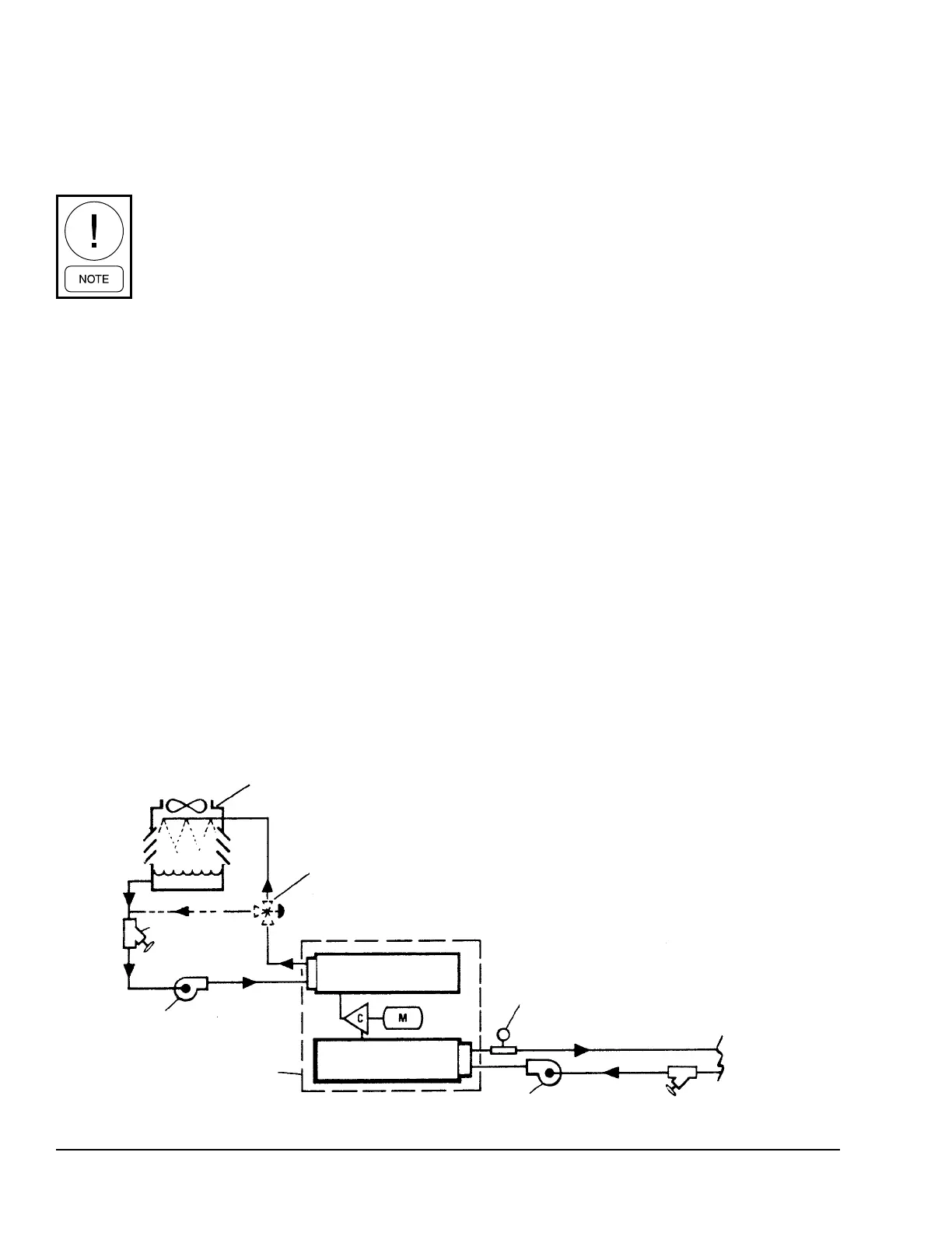
FIGURE 8 - SCHEMATIC OF A TYPICAL PIPING ARRANGEMENT
LD08529
EVAPORATOR
CONDENSER
STRAINER
STRAINER
COOLING
TOWER
COOLING
UNIT
C = COMPRESSOR
M = MOTOR
FLOW SWITCH
CHILLED WATER PUMP
COOLING TOWER
PUMP
COOLING UNIT
CODEPAK
CONTROLLED COOLING
TOWER BYPASS VALVE
(IF NECESSARY)

 Loading...


