JOHNSON CONTROLS
21
SECTION 2 - INSTALLATION
FORM 160.75-N1
ISSUE DATE: 04/15/2019
2
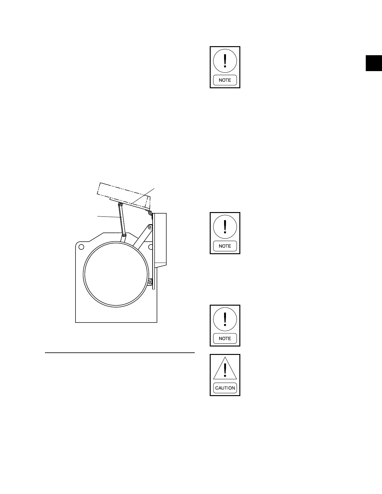
CONTROL PANEL POSITIONING
On large YK chillers equipped with H9 and K1-K7
compressors, the control panel height can be adjusted.
Chillers equipped with P and Q compressors the
control panel height is NOT adjustable. The OptiV-
iew™ Control Center is placed in a position above the
evaporator for shipping. To move the control center
into position for operation, proceed as follows:
1. While supporting the control center, remove the
hardware between the support arms and the evap-
orator.
2. Swing the control center into a vertical position.
3. Slide the control center down the guide rails to the
proper position. Tighten securely.
4. Discard unused hardware.
FIGURE 10 - CONTROL PANEL POSITIONING
(H9, K1-K7)
LD03826
CONTROL WIRING
On units shipped disassembled, after installation of the
control center, control wiring must be completed be-
tween unit components and control center, solid state
starter, or variable speed drive, when used, using wir-
ing harnesses furnished. Refer to Installation and Re-
assembly - Unit (Form 160.75-N3).
Field wiring connections for commonly encountered
control modifications (by others) if required, are
shown on Wiring Diagrams – Field Control Modifica-
tions (Form 160.75-PW4).
No deviations in unit wiring from that
shown on drawings furnished shall be
made without prior approval of the John-
son Controls representative.
POWER WIRING
Chiller with Electromechanical Starter
A 115 volt – single phase – 60 or 50 Hertz power sup-
ply of 20 amperes must be furnished to the control
center, from the control transformer (2 KVA required)
included with the compressor motor starter. Do NOT
make final power connections to control center until
approved by YORK representative.
OIL PUMP – 3 PHASE STARTER
Separate wiring or a fused disconnect switch should be
supplied by the installer.
Remote Electromechanical starters for
the chiller must be furnished in accor-
dance with YORK Starter Specications
Product Drawing Form 160.73-PA1 to
provide the features necessary for the
starter to function properly with the
YORK control system.
Each chiller unit is furnished for a specific electrical
power supply as stamped on the Unit Data Plate, which
also details the motor connection diagrams.
To insure proper motor rotation the starter
power input and starter to motor con-
nections must be checked with a phase
sequence indicator in the presence of the
Johnson Controls representative.
DO NOT cut wires to nal length or make
nal connections to motor terminals or
starter power input terminals until ap-
proved by the Johnson Controls repre-
sentative.
YK Motors (Electromechanical Starter)
Motor leads are furnished with a crimp type connection
having a clearance hole for a 3/8" bolt, motor terminal
lugs are not furnished. Refer to Wiring Labels in mo-
tor terminal box for hook-up to suit motor voltage and
amperage for power wiring connections.

 Loading...


