JOHNSON CONTROLS
22
FORM 160.75-N1
ISSUE DATE: 04/15/2019
SECTION 2 - INSTALLATION
Chiller with Solid State Starter or Variable
Speed Drive
A chiller equipped with a factory mounted Solid State
Starter or Variable Speed Drive does not require wir-
ing to the compressor motor. The motor power wiring
is factory connected to the Solid State Starter or Vari-
able Speed Drive. Refer to Field Wiring Diagram. All
wiring to the control panel and the oil pump starter is
completed by the factory. A control transformer is fur-
nished with the Solid State Starter or Variable Speed
Drive.
Copper Conductors – Only copper conduc-
tors should be connected to compressor
motors and starters. Aluminum conductors
have proven to be unsatisfactory when
connected to copper lugs. Aluminum oxide
and the difference in thermal conductivity
between copper and aluminum cannot
guarantee the required tight connection
over a long period of time.
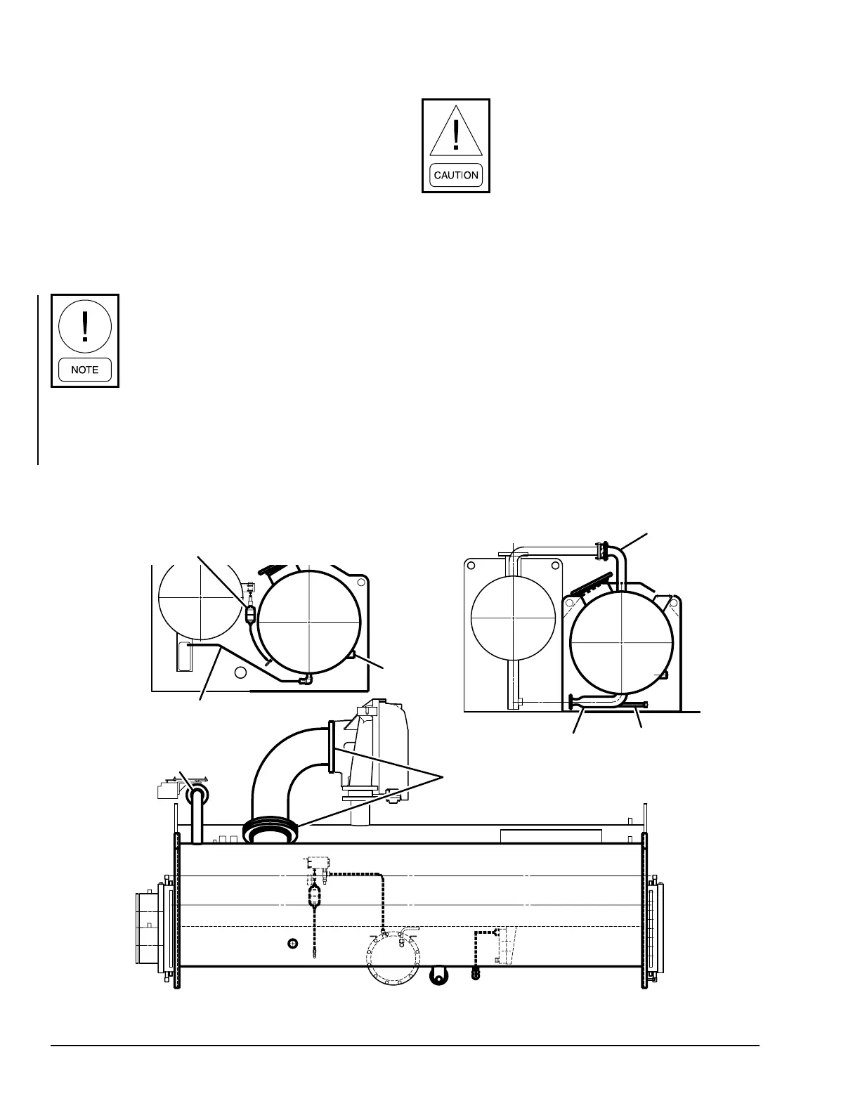
INSULATION
DO NOT eld insulate until the unit has
been leak tested under the supervision of
the Johnson Controls representative.
Insulation of the type specified for the job, or mini-
mum thickness to prevent sweating of 30°F (-1°C)
surfaces should be furnished (by others) and applied
to the evaporator shell, end sheets, liquid feed line to
flow chamber, compressor suction connection, and
evaporator liquid heads and connections. The liquid
head flange insulation must be removable, to allow
head removal for the tube maintenance. Details of ar-
eas to be insulated are given on the Product Drawing.
Units are furnished factory anti-sweat insulated on or-
der at additional cost. This includes all low tempera-
ture surfaces except the two (2) cooler liquid heads.
FIGURE 11 - UNIT INSULATION
LD12649
Input Drain
and
Charging
Connection
Liquid Line
NOTE: Bold lines represent Insulation
2” Liquid
Level Indicator
to Filter Drier
Refigerant from
Oil Cooler to Cooler
Hot Gas
Connection
Tape Insulation
around flanges to
allow for removal
CONDENSER
CONDENSER
EVAPORATOR
EVAPORATOR

 Loading...


