JOHNSON CONTROLS
6
FORM 160.75-N1
ISSUE DATE: 04/15/2019
LIST OF FIGURES
LIST OF TABLES
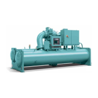
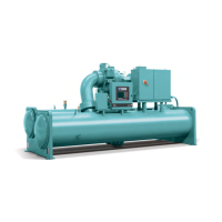
FIGURE 1 - Model YK Chiller ....................................................................................................................................7
FIGURE 2 - Variable Speed Drive Rigging ................................................................................................................9
FIGURE 3 - Long Term Storage - Tube Side ...........................................................................................................10
FIGURE 4 - Rigging.................................................................................................................................................13
FIGURE 5 - Neoprene Isolators ..............................................................................................................................14
FIGURE 6 - Spring Isolators ...................................................................................................................................15
FIGURE 7 - Spring Isolators ...................................................................................................................................16
FIGURE 8 - Schematic of a Typical Piping Arrangement ........................................................................................18
FIGURE 9 - Typical Refrigerant Vent Piping ............................................................................................................20
FIGURE 10 - Control Panel Positioning (H9, K1-K7) ..............................................................................................21
FIGURE 11 - Unit Insulation ....................................................................................................................................22
FIGURE 12 - Dimensions – P and Q Compressor Units (Ft–In) .............................................................................25
FIGURE 13 - Dimensions – P and Q Compressor Units (mm) ................................................................................26
FIGURE 14 - Dimensions – H Compressor Units (Ft–In) ........................................................................................ 27
FIGURE 15 - Dimensions – H Compressor Units (mm) ..........................................................................................28
FIGURE 16 - Dimensions – K Compressor Units (Ft–In) ........................................................................................29
FIGURE 17 - Dimensions – K Compressor Units (mm) ..........................................................................................30
FIGURE 18 - Dimensions – Evaporator Compact Waterboxes ..............................................................................31
FIGURE 19 - Dimensions – Condenser Compact Waterboxes ..............................................................................32
FIGURE 20 - Dimensions – Evaporator Compact Waterboxes A through L Evaporators .......................................33
FIGURE 21 - Dimensions – Evaporator Compact Waterboxes M through Z Evaporators ...................................... 34
FIGURE 22 - Dimensions – Condenser Compact Waterboxes - A through Q -Standard (mm) .............................. 35
FIGURE 23 - Dimensions – Condenser Compact Waterboxes - R through Z - Standard (mm) ............................. 36
FIGURE 24 - Dimensions – Condenser Heat Recovery Compact Waterboxes - Standard (mm) ........................... 37
FIGURE 25 - Dimensions – Evaporator Nozzle Arrangements - Standard (mm) ....................................................38
FIGURE 26 - Dimensions – Condenser Nozzle Arrangements - Standard (mm) ....................................................39
FIGURE 27 - Dimensions – Evaporator Marine Waterboxes .................................................................................40
FIGURE 28 - Dimensions – Condenser Marine Waterboxes .................................................................................41
TABLE 1 - Available Compressor/Shell/Motor Combinations .................................................................................23
TABLE 2 - Approximate Unit Weight Including Motor for Flooded Evaporator Units - Lb (kg) ................................44
TABLE 3 - Approximate Unit Weight Including Motor for Hybrid Falling Film Evaporator Units - Lb (kg) ..............45
TABLE 4 - Evaporator Marine Waterbox Weights - Lb (kg) ...................................................................................45
TABLE 5 - Condenser Marine Waterbox Weights - Lb (kg) ...................................................................................46
TABLE 6 - SI Metric Conversion .............................................................................................................................47

 Loading...


