www.modelflight.com.au – World’s best source of JR products
.
4
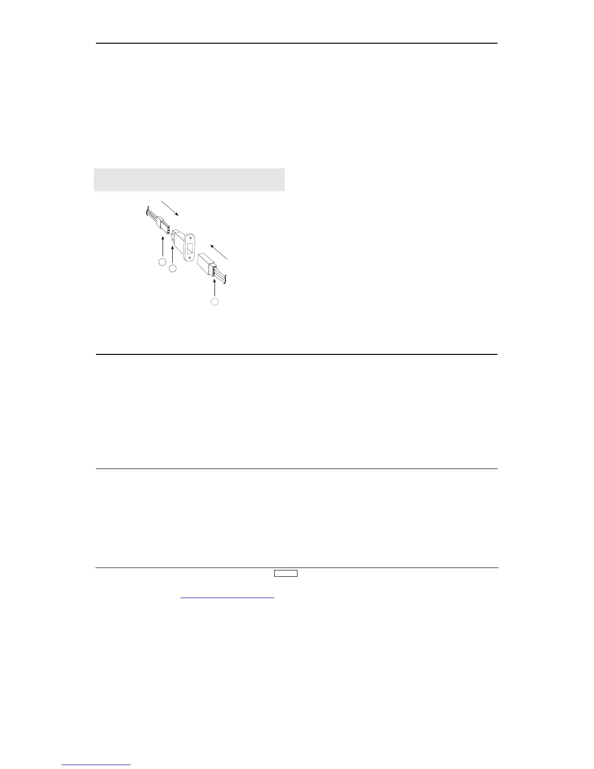
DSC Cord
For proper DSC hook up and operation:
1.
Leave the transmitter power switch in the OFF position. The
transmitter will not transmit any radio frequency (RF) in this
position.
2.
Plug the DSC cord (optional) into the DSC port in the rear of
the transmitter
.
3.
The encoder section of the transmitter will now be
operational and the LCD display will be lit.
4.
Plug the other end of the DSC cord into the receiver charge
receptacle. T
ur
n
the switch har
ness to the ON position.
Note:
The DSC function will only operate with the JRP
A00
1
Deluxe Switch Har
ness, or the JRP
A004 Charge Switch.
When you install the charging jack, be sure to hook the charging
ack receptacle securely into the switch harness charge
cord.
Why you should use the DSC function:
1.
The DSC enables you to check the control sur
faces of your
airplanes without drawing the fully operational 2
00 mAh from
your transmitter batter
y pack. Instead, you will only draw 7
0
mAh when using the DSC function.
2.
The DSC function allows you to make final adjustments to
your airplane without transmitting any radio signals. Therefore, if
another pilot is flying on your frequency, you can still adjust your
airplane and not interfere with the other pilot’s aircraft.
Note:
Under no circumstances should you attempt to fly your
airplane with the DSC cord plugged in! This function is for
bench checking your airplane only
.
B
. Charge cord/DSC receptacle
B. Switch har
ness lead
C. Char
n eyelet is provided on the face of the XP8
10
3 transmitter
which allows you to connect a neck strap (JRP
A0
2
3). This hook
has been positioned so that your transmitter has the best possible
balance when you use the neck strap.
Note:
Double check to ensure that the neck strap is securely
fastened to the transmitter
.
n optional base loaded antenna is available for use with the
XP8
10
3 transmitter
. It is considerably shor
ter than the standard
antenna. However
, the base loaded antenna cannot be
collapsed for storage in the side of the transmitter
. Y
ou must also
use an adaptor (JRP
A1
5
6) to attach the antenna to your XP8
10 3.
The base loaded antenna (JRP
A1
5
5) is made of a flexible coil
and is covered with a soft plastic material. Y
our range will not
be af
fected when using the base loaded antenna.