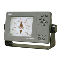
2-30
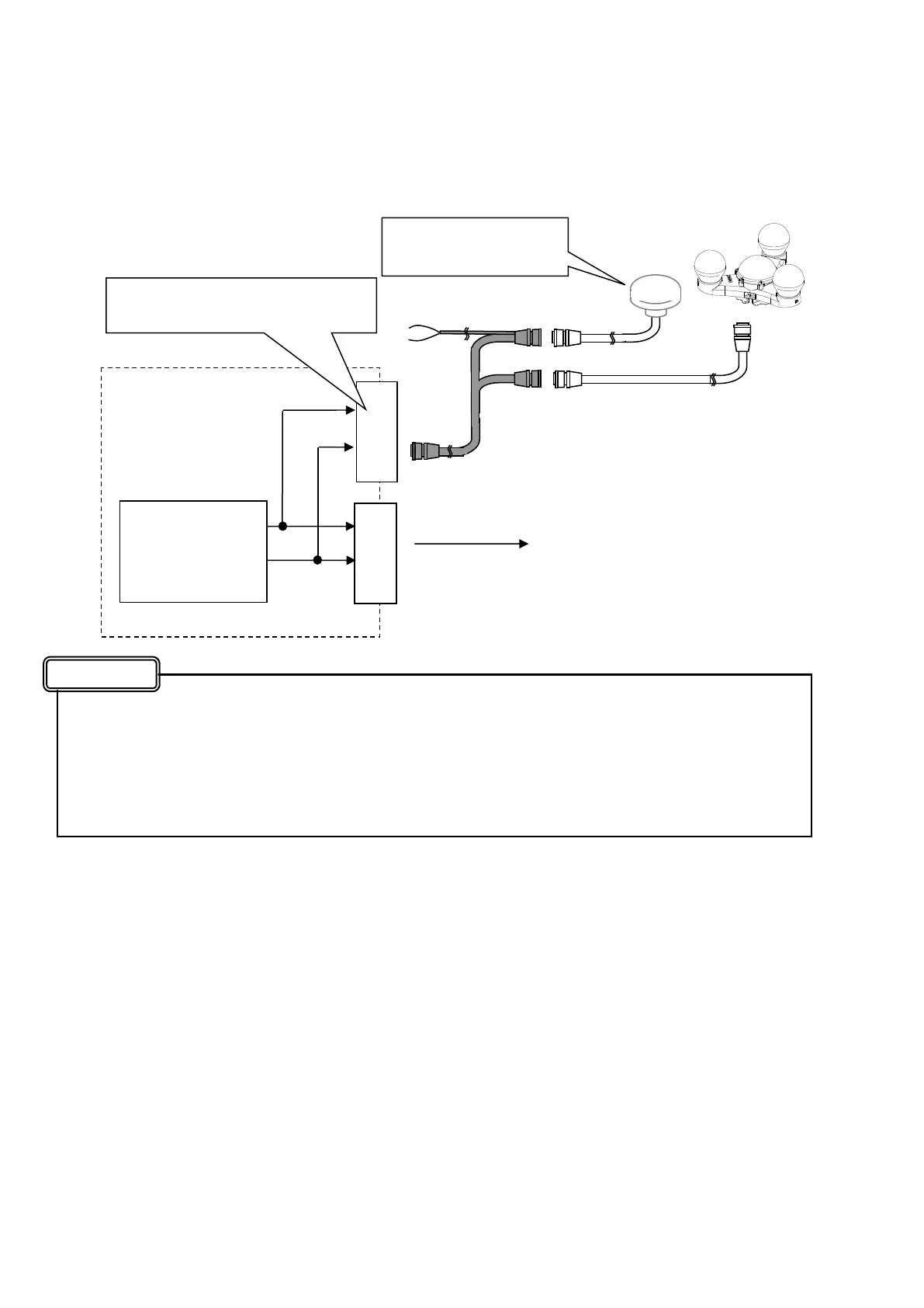
●Output connection of DATA OUT4 (9 and 10 pins of Data IN/OUT2 connector)
DATA OUT4 connects inside the display unit as shown in the following figure.
When connecting a beacon receiver, Data OUT4/IN4 port is set to beacon/**** and configuration
data is sent from the 11 and 12 pins of SENSOR connector to the beacon receiver; however, be
aware that, at that time, the same data (the configuration data to the beacon receiver) is also led
to the 9 and 10 pins of Data IN/OUT2 connector connected inside.
For this reason, do not connect external equipment to the output of the 9 and 10 pins of the Data
IN/OUT2 connector when using the beacon receiver.
・
11
12
・
・
9
10
・
Inner
NWZ-4701
Connect to external equipment
SENSOR
Connector
DATA IN/OUT2
Connector
DC12V
Configuration line to a DGPS
receiver (beacon) (11 and 12 pins)
JLR-4341 or JLR-4331
DGPS receiver
Data OUT4/ IN 4
Port
(This name for
in Display Unit)
CFQ-7250C
Cable
Attention