5-28
The reference
line for the
Z-direction
For the X- and Y-directions,
their references are the
center of the sensor unit (the
center of the processing unit
cover.)
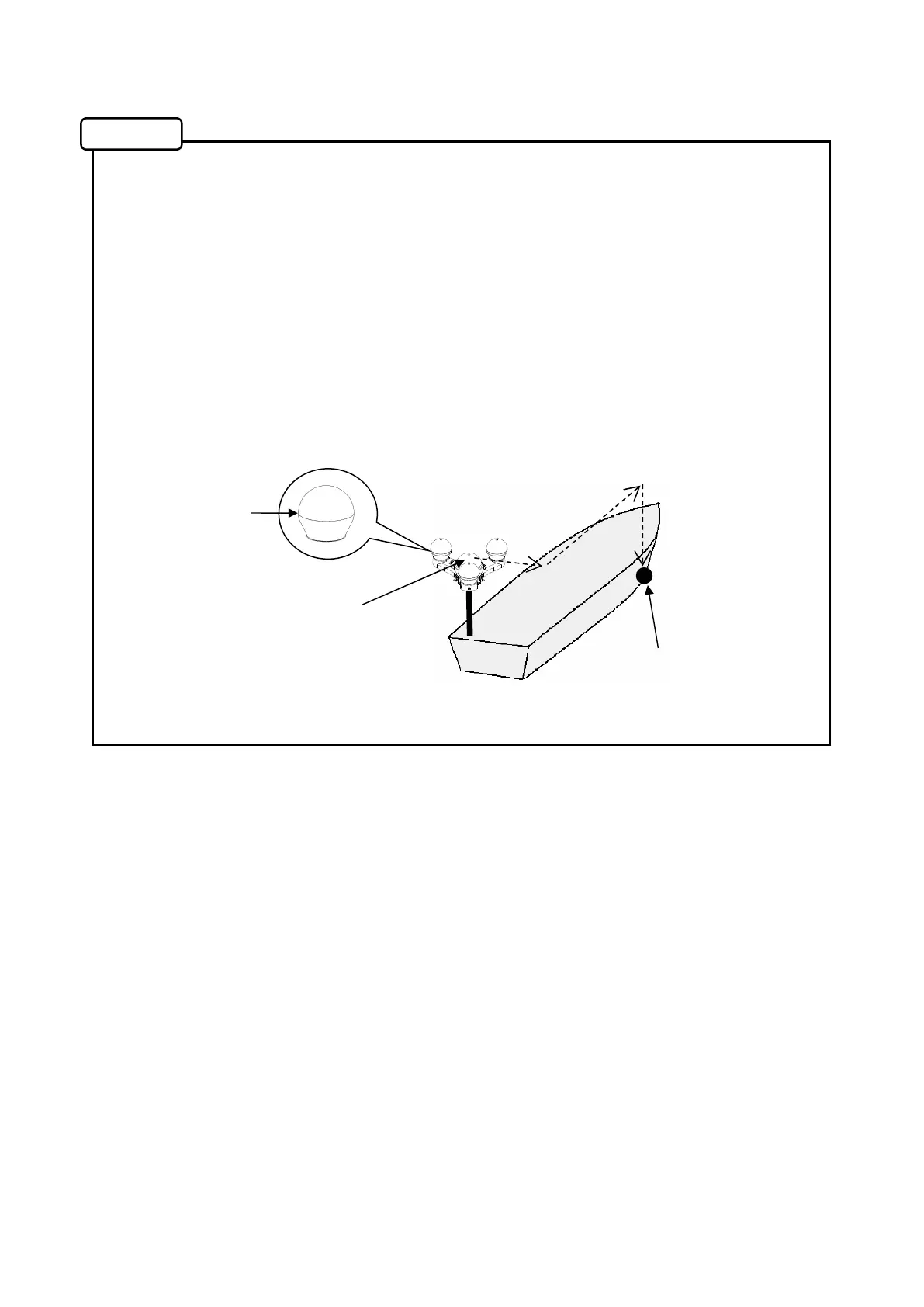
●Offset function for a heaving measuring position displayed on the display unit
All defaults in “HVE POINT OFFSET” are 0; in this case, the heaving measuring
position is the installation position of the sensor unit. The measuring position can be offset to
another position by the following procedure (as an example.)
1. Set offset values in “HVE POINT OFFSET” in “SYSTEM MENU”.
2. An example of the offset values (Refer to the following figure.)
・X-direction: 3m rightward (enter +3m)
・Y-direction: 10m forward (enter +10m)
・Z-direction: 3m downward (enter -3m)
3. The heaving display on the display unit will be the display at the offset position
(● in the following figure.)
(The offset setting is not applicable to the heaving data delivered to external devices.)
Memo
X = +3m
Y = + 10m
Z =-3m
Offsetting target