35
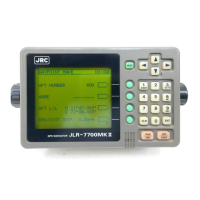
JLR-7700 MK2 GPS Navigator
3.4.8 Connection Cable (Optional Unit)
It is necessary to use the optional data cable shown in the table below if data needs to be output from the
[DATA OUT] connector described under the item 3.4.4 “Data Output”.
6-282-7SG-321
(CONXALL)
3 m
Data cable CFQ-8921
Unit Model Remarks
Terminal
1 Red : Data1 Out
2 Black : GND
3 Brown : Data2 + Out
4 Orange : Data2 ー Out
6 Yellow : Log Pulse +
7 Blue : Log Pulse ー
Terminal : Frame GND
Unit : mm
4.8 5.5
Rubber grommet
Back shell
Coupling ring
Socket contacts
O-ring
Connector body
3.4.7 Connection of the Waterproof Connectors (2, 6, or 7-pin Connector)
(1) Strip the cable end as shown in the figure below.
(2) Put the respective parts through the cable as shown in the assembly drawing.
(3) Solder the cable ends to the socket contacts, and cap the socket contact with the rubber grommet by
allowing it to slide on the contact body surface so that it will be securely covered.
(4) Put the O-ring through the connector body all the way to the end.
(5) Secure the back shell on the connector body.
(Align the notch provided on the back shell with the tab on the body and press them each other, then, turn
them to secure. It is recommended to insert the connector body into the navigator connector if the above
approach is found difficult.)
Stripping Dimensions on the Cable End
Assembly Drawing
 Loading...