– 105 –
6. Electrical component and the like
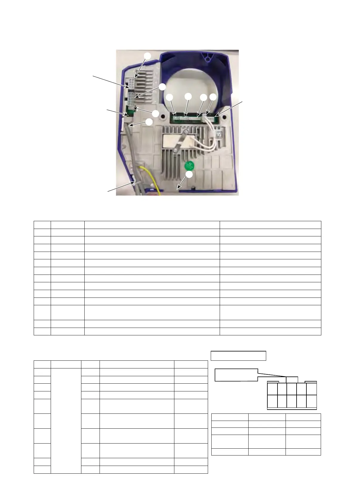
(1) Control BOX
Table 1 Input/output connector arrangement in control box
No. Connector Name of the destination to connect Remark
❶
J4 Regenerative resistor
❷
J6 Main motor power
❸
J7 Pedal sensor *
The connectors exist in the control box.
❹
J8 Main software rewrite
❺
J9 For production control
❻
J10 AC power input
The connectors exist in the control box.
❼
J12 LED hand light/hand switch
❽
J15 Panel I/F
❾
J17 Thread presser solenoid & optional output
❿
J18 Presser motor power/origin sensor
⓫
J19
Thread trimming, reverse feed solenoid/oil
quantity sensor
⓬
CN1 Main motor encoder
⓭
CN15 Presser motor software rewrite
* Applicable
onlytothestandardpedalspecication.Standingpedalspecicationisnotavailable.
Table 2 Optional connector pin arrangement
No.
Connector
Pin Item Remark
1
J17
1 Suctionsolenoidvalve(+)
2 2 Suctionsolenoidvalve(–)
3 3
Threadhaulingsolenoidvalve(+)
4 4
Threadhaulingsolenoidvalve(–)
5 5
Needle thread
holdingsolenoidvalve(+)
6 6
Needle thread
holdingsolenoidvalve(–)
7
7
Threadpressersolenoid(+)
Standard
functions
8
8
Threadpressersolenoid(–)
Standard
functions
9 9 Condensationsolenoid(+)
10 10 Condensationsolenoid(
–
)
❶
❼
⓬
⓭
❽
❻
❺
❸
⓫
❾
❹
❿
❷
1
2
3
4
5
68
79
10
Fastening claw
Housing arrangement
JUKI part No.:
HK034640000
HK034610100
Part name
Pin contact
Housing
Manufacturer Molex Inc Molex Inc
Model name of
manufacturer
5556T 5557-NR
Remark
This is different from the pin arrangement
specied
bythemanufacturer.
Refertothegureaboveforpinarrangement
numbers.
 Loading...