– 106 –
(2) Panel
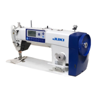
Table 3 Panel input/output connector arrangement
No. Connector Name of the destination to connect Remark
❶
J1 Main I/F
❷
J2 Membrane switch
❸
J2_1 Audio software rewrite
❹
J3 Panel software rewrite
❺
J5 Audio speaker
❻
B1 Clock battery
❼
USB USB
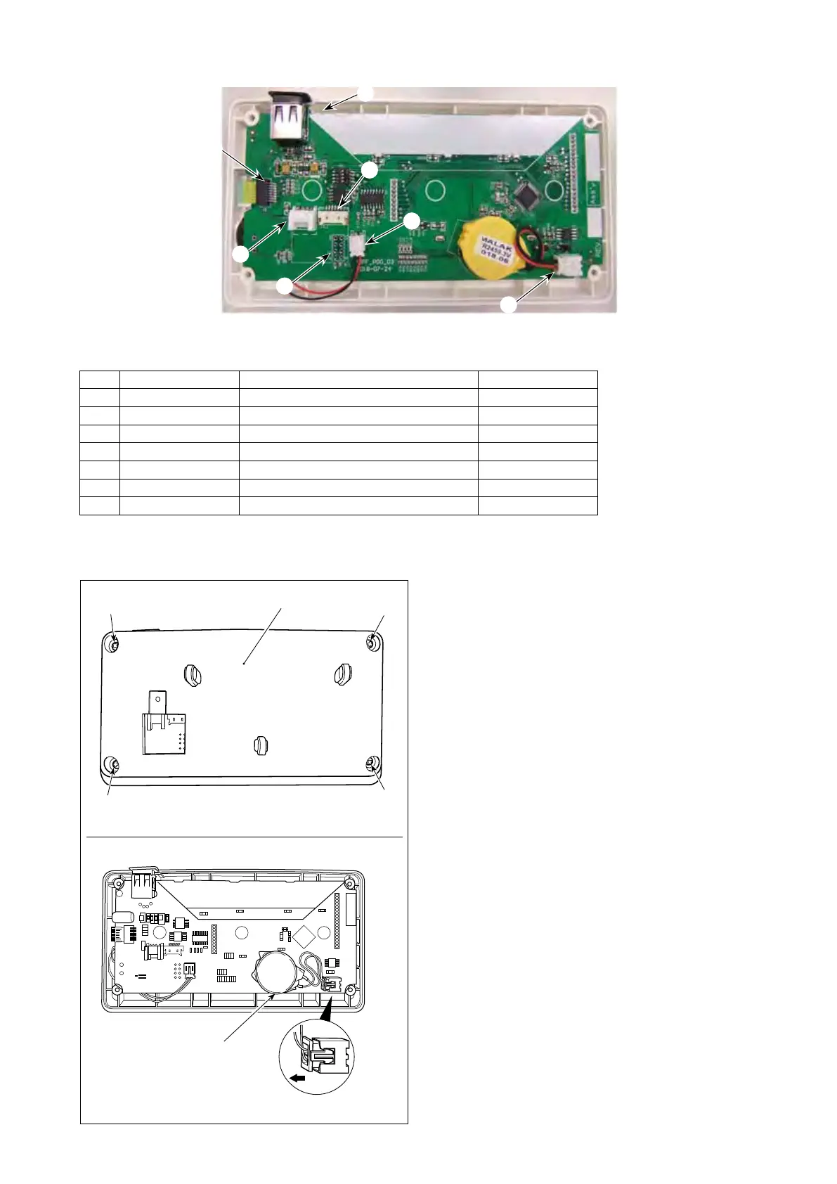
[How to remove the battery]
❼
❸
❷
❶
❹
❻
❺
1
) Removepanelfromthemainbodyofsewing
machine.
2
)
Loosen screw
❽
from the rear surface of the
operation panel. Detach case
❾
.
3
)
❿
is the battery for clock.
Type number: CR2450
4
)
Pull out the connector in the direction of A.
Detach the whole main body of battery together
withitscasefromthePCB.(Thebatteryis
secure on the PCB with double-faced adhesive
tape.)
(Caution)
The operation panel has a built-in battery
in order to operate the clock even when
the power is turned OFF.
Be sure to dispose of the battery following
the local laws and regulations.
❿
A
Type number : CR2450
❽
❽
❽
❽
❾
 Loading...