EasyManuals Logo

JUKI DDL-8000A Engineer's Manual

JUKI DDL-8000A
173 pages
To Next Page IconTo Next Page
To Previous Page IconTo Previous Page
Page #77 background imageLoading...
Page #77 background image
– 64 –
Adjustment Procedure
Results of Improper Adjustment
1) How to remove the control box
1. Remove all the setscrews from the rear cover.
2. Remove all the connectors connected to the control box.
3. Remove the earth cable connected to the head.
*Ifthescrewdrivertipisnotinsertedfullyintheslot,theange
part of the upper sprocket is deformed or destroyed.
4. Remove the setscrews and from the control box.
Screw part number
: SL4052591SC L=25
: SL4051691SC L=16
5. Assembly can be conducted by the reversed procedure.
(Cautions) Pay attention not to catch cords at the installation
of the control box.

Table of Contents

Other manuals for JUKI DDL-8000A

Questions and Answers:

Question and Answer IconNeed help?

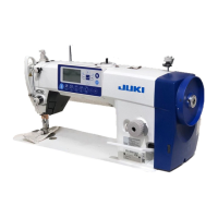
Do you have a question about the JUKI DDL-8000A and is the answer not in the manual?

JUKI DDL-8000A Specifications

General IconGeneral
Stitch TypeLockstitch
Motor TypeDirect-drive motor
Thread TrimmerAutomatic
Max. Stitch Length5mm
Needle Bar Stroke30.7mm
Lift of the Presser FootBy hand: 5.5mm, By knee: 13mm
Control PanelDigital
LubricationAutomatic

Related product manuals